DC9006A
AND
DC9004B
U
SER
G
UIDE
A
NALOG
D
EVICES
,
I
NC
.
C
ONFIDENTIAL
13
Usage
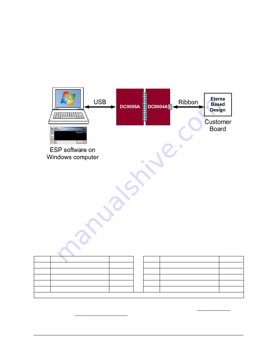
For a non-powered customer board, where the customer board is powered by the
VSUPPLY and GND signals of the DC9004, simply connect the ribbon cable.
For an independently powered customer board, first place the DC9006 JP7 jumper
(see
Figure 4) in the “OFF” position, then connect the ribbon cable. Note that in this
configuration the DC9006 will draw some power from the customer board to power
some of its circuitry.
Figure 7
Connecting an Eterna Design to the DC9004B
Interfaces
DC9006 Interface
The interface to the DC9006 consists of a 0.1” pitch 2x16 header with the same
signals described in section “Eterna Evaluation and Development Mote Socket
Pinout”.
Programming Interface Headers (2x5 0.050”, 2mm and .100” pitch)
The programming headers are indicated with the marking “ESP” on the DC9004B
silkscreen.
The following table describes the pinouts of P2 (MOLEX/87833-1020), P3
(SAMTEC/FTSH-105-01-F-DV-K) and P5 (SAMTEC/TST-105-04-L-D-RA).
Pin # Signal
Direction
Pin # Signal
Direction
1 IPCS_SSn
O
2 FLASH_P_ENn
O
3 IPCS_SCK
O
4 IPCS_MOSI
O
5 IPCS_MISO
I
6 RESETn
O
7 VSUPPLY
-
8 GND
-
9 UARTC0_TX/UARTC1_TX
I
10 UARTC0_RX/UARTC1_RX O
Signal direction is relative to the Programming Adapter board.
The .100” pitch programming connector (P5) is intended to be used in conjunction
with the TC2050-IDC cable from Tag-Connect, described in
http://www.tag-
connect.com/TC2050-IDC
.


