EVAL-AD5340DBZ User Guide
UG-981
Rev. 0 | Page 5 of 13
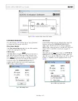
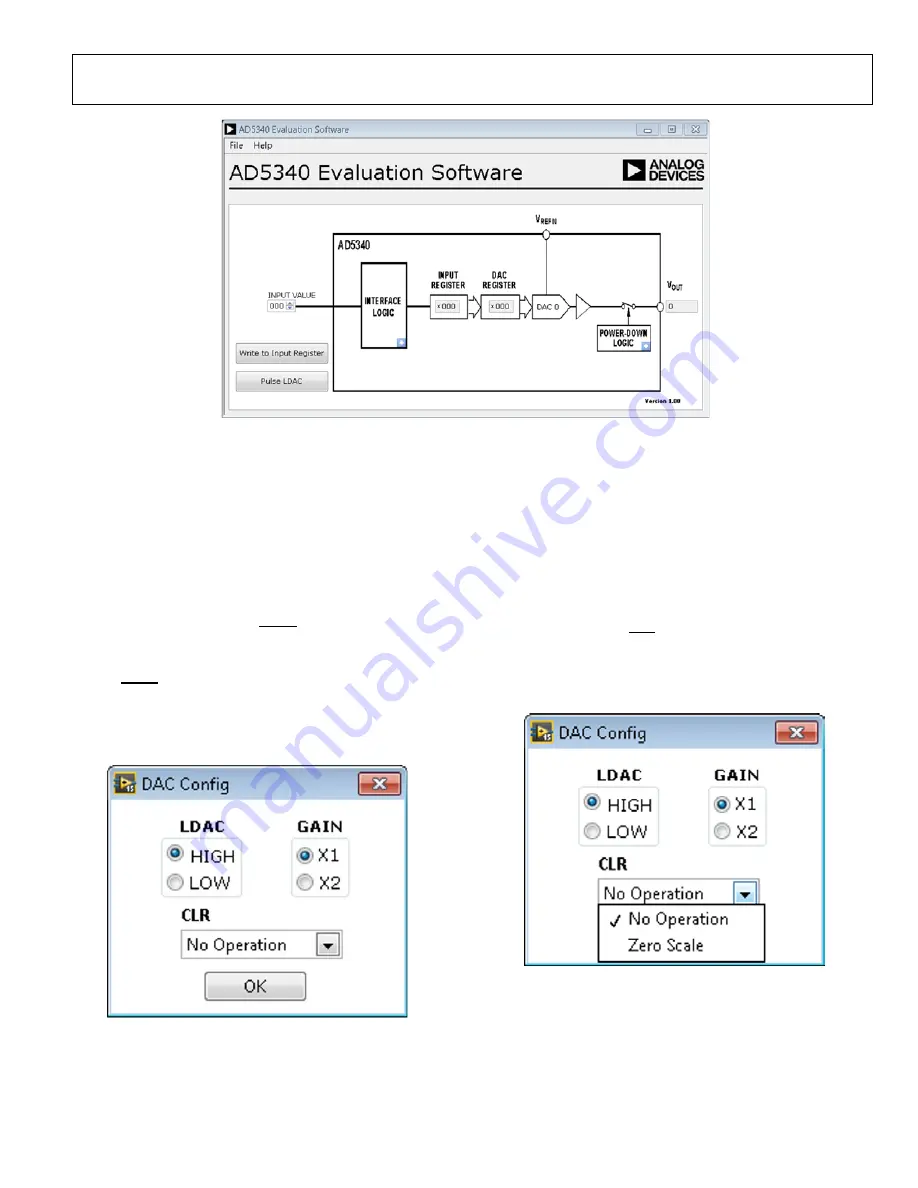
Figure 4.
AD5340
Evaluation Board Software Main Window
SOFTWARE OPERATION
The software for the
AD5340
allows the user to program values
to the input and DAC registers of the DAC.
Write to Input Register
Click
Write to Input Register
to load the code of the input data
control to the input register of the DAC.
LDAC Control
Click
Pulse LDAC
to bring the LDAC pin low and then back to
high. Doing this copies the data from the input register to the
DAC register, and the output updates accordingly. Alternatively,
set the LDAC pin high or low by clicking the blue progressive
disclosure button on the
INTERFACE LOGIC
block. A
window opens that allows the user to click the appropriate
LDAC
setting, as shown in Figure 5.
Figure 5.
DAC Config
Window
GAIN Control
Set the GAIN pin high or low by clicking the blue progressive
disclosure button on the
INTERFACE LOGIC
block. A
window opens that allows the user to click the appropriate
GAIN
setting, as shown in Figure 5. Click
X1
to set a full-scale
output of 2.5 V or click
X2
to set a full-scale output of 5 V.
CLR Control
Click the blue progressive disclosure button on the
INTERFACE
LOGIC
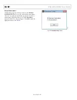
block to set the CLR pin setting. A window opens that
allows the user to select the
CLR
setting for the DAC, as shown
in Figure 6. Click
OK
to write the appropriate values to the
AD5340
.
Figure 6.
CLR
Setting Dropdown Box
14516-
004
14516-
005
14516-
001

