background image

EVAL-ADAQ8088EBZ

 User Guide 

UG-1825


Rev. 0 | Page 7 of 12 

EVALUATING THE ADAQ8088 BY DRIVING THE AD9681 ADC 

CONFIGURING THE EVAL-ADAQ8088EBZ, 
AD9681-125EBZ, AND HSC-ADC-EVALEZ 

Before using the software for testing, take the following steps 
to configure the EVAL-ADAQ8088EBZ, AD9681-125EBZ, 
and HSC-ADC-EVALEZ: 

1.


Take the following steps to modify the EVAL-
ADAQ8088EBZ: 
a.


Remove the R5, R6, R7, and R8 resistors. 

b.


Install a 40 Ω resistor on R5, R6, R7, and R8. 

2.


Take the following steps to modify the AD9681-125EBZ 
(FMC connector version) of each channel selected (Figure 6 
shows Channel A1 and Channel A2 selected for use):  
a.


Install an SMA connector on the J102 and J104 
ports. 

b.


Remove the R14, R16, C3, C4, J6, J7, C7 to C10, 
R36, to R39, and T17 to T20. 

c.


Install a 0 Ω resistor on R321, R415, C3, C4, J6, J7, 
C7 to C10, and R36 to R39. 

d.


Connect a jumper wire from Pin 3 to Pin 4 of T1.  

e.


Connect a jumper wire from Pin 1 to Pin 6 of T1. 

f.


Connect a jumper wire from Pin 3 to Pin 4 of T2. 

g.


Connect a jumper wire from Pin 1 to Pin 6 of T2.  

3.


Connect the EVAL-ADAQ8088EBZ to the AD9681-
125EBZ, as shown in Figure 6, and then connect the 
AD9681-125EBZ to the HSC-ADC-EVALEZ by aligning 
each of their field programmable gate array mezzanine 
card (FMC) connector  and carefully press them together. 
Note that FMC connectors often come from the factory 
with a sticker that prevents connection. Remove this sticker 
(if needed) before attempting to make the connection. 

4.


On the EVAL-ADAQ8088EBZ, confirm that the jumpers 
are installed as shown in Figure 8.  

5.


Connect one 6 V, 2.5 A switching power supply (such as 
the CUI, Inc., EPS060250UH-PHP-SZ supplied in the 
AD9681-125EBZ evaluation kit) to the AD9681-125EBZ. 

6.


Connect the 12 V, 3.3 A switching power supply to the 
HSC-ADC-EVALEZ board. 

7.


Connect the HSC-ADC-EVALEZ to the PC using a USB 
cable (supplied in the HSC-ADC-EVALEZ evaluation kit). 

8.


On the EVAL-ADAQ8088EBZ, replace the value of R5, 
R6, R7, and R8 with 40 Ω each and use a clean signal 
generator with low phase noise to provide an input signal. 

9.


Connect the output signal from either J5 and J7 or J6 
and J8 to the selected channel of the AD9681-125EBZ.  

MEASUREMENT RESULTS WHEN DRIVING THE 
AD9681 USING THE ADAQ8088 AS A DRIVER 

The configurations of the EVAL-ADAQ8088EBZ and the 
AD9681-125EBZ used during testing include the following: 


The input source dual-channel generator (Keysight 
33600A differential signal generator) is set to 6 MHz, 
52 mV p-p for −1 dbFS. 


The input filter (Allen Avionics low-pass filter (LPF), 
F3056-7P7) is set to a 7.7 MHz cutoff frequency. Another 
LPF can be selected with a cutoff frequency above the input 
frequency and below the first harmonic. 


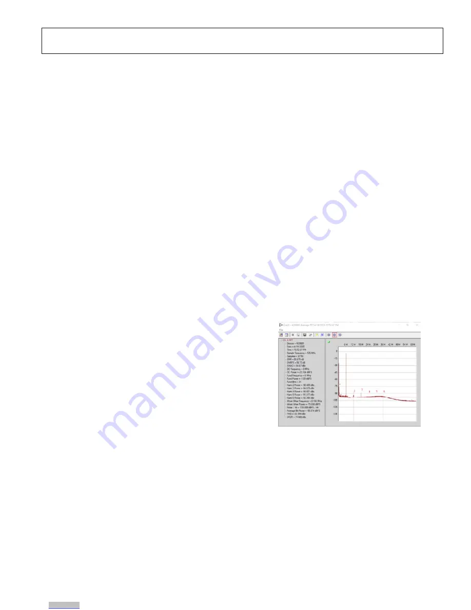
The I-channel and Q-channel are driven and measured 
(refer to Figure 6). A sample FFT of the measurement is 
shown in Figure 5. 


The output loading is configured as follows: 


10 Ω internal to μModule.  


40 Ω on the EVAL-ADAQ8088EBZ. 


33 Ω and 5 pF LPF on the EVAL-ADAQ8088EBZ 
(still allows for optimization).  

For details on the correct EVAL-ADAQ8088EBZ jumper 
positions, modes of operation, and using the ADC data 
capture software for testing, see the AD9681-125EBZ user 
guide page at 

https://wiki.analog.com/resources/eval/ad9681-

125ebz


Figure 5. Fast Fourier Transform (FFT) Result  

25399-

008

Downloaded from

Arrow.com.

Downloaded from

Arrow.com.

Downloaded from

Arrow.com.

Downloaded from

Arrow.com.

Downloaded from

Arrow.com.

Downloaded from

Arrow.com.

Downloaded from

Arrow.com.

Summary of Contents for EVAL-ADAQ8088EBZ

Page 1: ...cs LPF F3056 7P7 2 pieces PC running Windows GENERAL DESCRIPTION The EVAL ADAQ8088EBZ evaluates the ADAQ8088 and requires a 2 7 V to 3 3 V power supply for proper operation The EVAL ADAQ8088EBZ accepts baseband differential in phase quadrature I Q inputs via Subminiature A SMA connectors Jx and drives pipeline analog to digital converters ADCs via SMA output connectors The EVAL ADAQ8088EBZ contain...

Page 2: ...ibration Procedure 4 Magnitude and Frequency Response Measurements Using A Two Port Network Analyzer 5 Measuring the Magnitude and Frequency Response of the I Channel 5 Measuring the Magnitude and Frequency Response of the Q Channel 6 Calibration Procedure 6 Evaluating the ADAQ8088 by Driving the AD9681 ADC 7 Configuring the EVAL ADAQ8088EBZ AD9681 125EBZ and HSC ADC EVALEZ 7 Measurement Results w...

Page 3: ... 1 Jumper Details with Factory Default Settings Link Default Function Comment P1 Not populated VS ADAQ8088 supply P2 Not populated EXVCMA Connect EXVCMA to the common mode output of the ADC I channel This jumper can also be left floating P3 Not populated EXVCMB Connect EXVCMB to the common mode output of the ADC Q channel This jumper can also be left floating Note that the I channel and the Q chan...

Page 4: ... the output phase on Port 3 and Port 4 of the network analyzer CALIBRATION PROCEDURE First ensure that the four port network analyzer is calibrated using either the ECal electronic calibration module or the manual short open and load method When the network analyzer is calibrated using one of these two methods take the following steps to complete the network analyzer through calibration 1 Use an S...

Page 5: ...e network analyzer 4 To measure the frequency response at the I_OUTN output of the EVAL ADAQ8088EBZ take the following steps a Use an SMA cable to connect J5 of the EVAL ADAQ8088EBZ to Port 2 of the network analyzer b Terminate J7 to 50 Ω c Set the network analyzer output Port 1 to a power level of 20 dBm d Observe the frequency response on Port 2 of the network analyzer I_INN as the Active Input ...

Page 6: ...d Observe the frequency response on Port 2 of the network analyzer Q_INN as the Active Input To measure the magnitude and frequency response of the Q channel with the Q_INN input as the active input and using a two port network analyzer see Figure 4 take the following steps 1 Use an SMA cable to connect J3 of the EVAL ADAQ8088EBZ to Port 1 of the network analyzer 2 Leave J4 of the EVAL ADAQ8088EBZ...

Page 7: ...PHP SZ supplied in the AD9681 125EBZ evaluation kit to the AD9681 125EBZ 6 Connect the 12 V 3 3 A switching power supply to the HSC ADC EVALEZ board 7 Connect the HSC ADC EVALEZ to the PC using a USB cable supplied in the HSC ADC EVALEZ evaluation kit 8 On the EVAL ADAQ8088EBZ replace the value of R5 R6 R7 and R8 with 40 Ω each and use a clean signal generator with low phase noise to provide an in...

Page 8: ...e analog input frequency if noncoherent sampling is used Ensure that the SPI configuration file matches the device being evaluated For further details on troubleshooting while evaluating the ADAQ8088 by driving the AD9681 ADC see the AD9681 125EBZ user guide page at https wiki analog com resources eval ad9681 125ebz 25399 006 3V BENCH SUPPLY EVAL ADAQ8088EBZ AD9681 125EBZ HSC ADC EVALEZ LPF DIFFER...

Page 9: ...10 VCC D4 VCC D5 VCC D6 VCC D7 VCC D8 VCC D9 VCC D10 VCC A2 DNC A3 DNC A5 DNC A6 DNC A10 DNC A11 DNC C2 DNC C3 DNC C11 DNC D2 DNC D3 DNC D11 DNC F2 DNC F3 DNC F5 DNC F6 DNC F10 DNC F11 DNC R14 0 2 1 3 4 5 R13 I_INP I_INN R1 J1 J2 2 1 3 4 5 R15 0 R16 1 0 Q_INP Q_INN J4 2 1 3 4 5 J3 R3 0 61 9Ω 61 9Ω R4 R2 61 9Ω 61 9Ω INPUT COMMON MODE VOLTAGE VCM POWER SUPPLY 5 1 4 3 2 AGND AGND AGND AGND I CHANNEL ...

Page 10: ...AL ADAQ8088EBZ Power Plane 25399 027 25399 028 Downloaded from Arrow com Downloaded from Arrow com Downloaded from Arrow com Downloaded from Arrow com Downloaded from Arrow com Downloaded from Arrow com Downloaded from Arrow com Downloaded from Arrow com Downloaded from Arrow com Downloaded from Arrow com ...

Page 11: ...ayer 25399 029 Downloaded from Arrow com Downloaded from Arrow com Downloaded from Arrow com Downloaded from Arrow com Downloaded from Arrow com Downloaded from Arrow com Downloaded from Arrow com Downloaded from Arrow com Downloaded from Arrow com Downloaded from Arrow com Downloaded from Arrow com ...

Page 12: ... entity other than ADI Customer their employees affiliates and in house consultants The Evaluation Board is NOT sold to Customer all rights not expressly granted herein including ownership of the Evaluation Board arereservedby ADI CONFIDENTIALITY This Agreement andthe Evaluation Board shall all be consideredtheconfidential and proprietary information of ADI Customer may notdiscloseortransferanypor...

Reviews: