


Analog 120-Pin Probing Board Manual
1-3
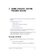
Using Analog 120-Pin Probing Board
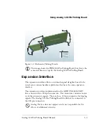
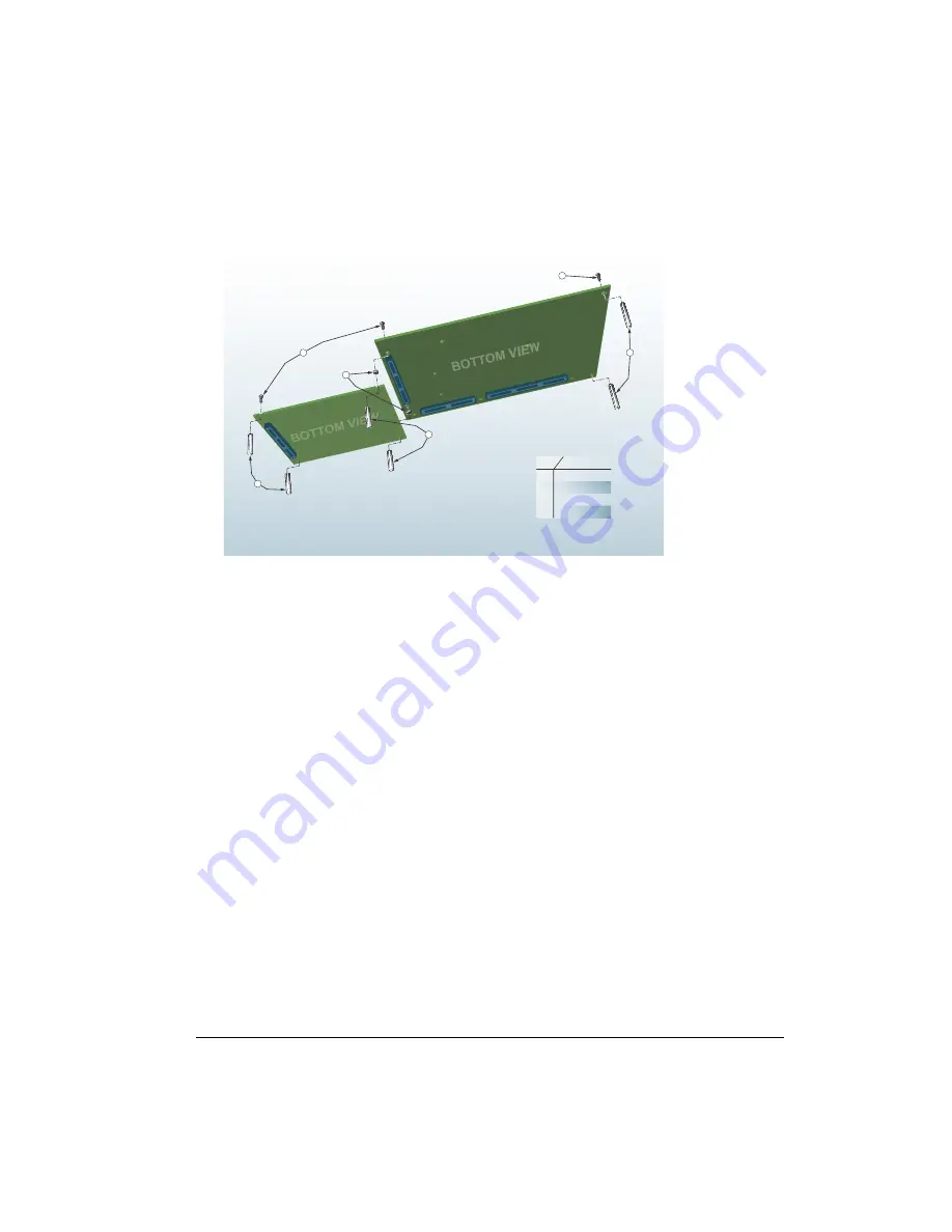
This image shows the PWM 180-Pin Probing Board, but this is the
same attachment setup for the Analog 120-Pin Probing Board.
Expansion Interface
The expansion interface allows a custom-designed daughter board to be
tested across various hardware platforms that have the same expansion
interface.
The expansion interface implemented on the ADSP-CM40x EZ-KIT
Lites consists of two 180-pin connectors. The connectors contain a major-
ity of the processor’s signals. There is also a 120-pin connector for Analog
signals. The Analog 120-Pin Probing Board should not be connected to
the 180-pin connectors.
Analog Devices does not support and is not responsible for the
effects of additional circuitry.
Figure 1-1. Mechanical Mating Details
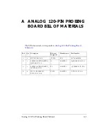
Part Description
Item
0.75in Nylon Standoff
1
1.0in Nylon Standoff
2
3
Steel Screw
4
Nylon Spacer
1
1
2
3
4
3
Summary of Contents for EZ-Extender ADSP-CM408 Series
Page 4: ......
Page 14: ...Notation Conventions xiv Analog 120 Pin Probing Board Manual ...
Page 22: ...Connectors 2 4 Analog 120 Pin Probing Board Manual ...
Page 24: ...A 2 Analog 120 Pin Probing Board Manual ...
Page 25: ...A B 4 3 2 ANALOG 12 ...
Page 28: ...Index I 2 Analog 120 Pin Probing Board Manual ...


