background image

Connectors

2-2

Analog 120-Pin Probing Board Manual

Connectors

This section describes connector functionality and provides information 
about mating connectors. The connector locations are shown in 

Figure 2-1

.

Figure 2-1. Connector Locations

Summary of Contents for EZ-Extender ADSP-CM408 Series

Page 1: ...a Analog 120 Pin Probing Board Manual an EZ Extender product Revision 1 0 September 2013 Part Number 82 000388 01 Analog Devices Inc One Technology Way Norwood Mass 02062 9106 ...

Page 2: ...ieved to be accurate and reliable However no responsibility is assumed by Analog Devices for its use nor for any infringement of patents or other rights of third parties which may result from its use No license is granted by impli cation or otherwise under the patent rights of Analog Devices Inc Trademark and Service Mark Notice The Analog Devices logo EngineerZone EZ Extender and EZ KIT Lite are ...

Page 3: ...al equipment or RF devices The Analog 120 Pin Probing Board is in the process of being certified to comply with the essential requirements of the European EMC directive 2004 108 EC and therefore carries the CE mark The probing board contains ESD electrostatic discharge sensitive devices Electrostatic charges readily accumulate on the human body and equipment and can discharge without detection Per...

Page 4: ......

Page 5: ...E Product Overview vii Purpose of This Manual viii Intended Audience viii Manual Contents ix What s New in This Manual ix Technical Support x Supported Products x Product Information xi Analog Devices Web Site xi EngineerZone xii Notation Conventions xii ...

Page 6: ...ard Installation 1 2 Expansion Interface 1 3 Reference Design Information 1 4 ANALOG 120 PIN PROBING BOARD HARDWARE REFERENCE System Architecture 2 1 Connectors 2 2 Connector J1 2 3 Connector P1 2 3 Connector P2 P5 2 3 Connector P7 P14 2 3 ANALOG 120 PIN PROBING BOARD BILL OF MATERIALS ANALOG 120 PIN PROBING BOARD SCHEMATIC INDEX ...

Page 7: ...l of the neces sary hardware you can start the evaluation immediately Product Overview The Analog 120 Pin Probing Board is a separately sold extender board that plugs onto the ADSP CM403F and ADSP CM408F EZ KIT Lite evaluation systems The extender board aids the design and prototyping phases of processor targeted applications The board extends the capabilities of the evaluation system by providing...

Page 8: ... A schematic and a bill of materi als are provided for reference Intended Audience The primary audience for this manual is a programmer who is familiar with an ARM Cortex M4 based core The ADSP CM40x family of mixed signal control processors is based on the ARM Cortex M4 processor core with floating point unit and inte grated SRAM memory flash memory accelerators and peripherals The applicable doc...

Page 9: ...it the ARM Information Center http infocenter arm com help Manual Contents The manual consists of Chapter 1 Using Analog 120 Pin Probing Board Describes the product functionality Chapter 2 Analog 120 Pin Probing Board Hardware Reference Provides information about the board s hardware components Appendix A Analog 120 Pin Probing Board Bill Of Materials Lists the hardware components used to manufact...

Page 10: ... support E mail your questions about processors and processor applications to processor support analog com or processor china analog com Greater China support In the USA only call 1 800 ANALOGD 1 800 262 5643 Contact your Analog Devices sales office or authorized distributor Locate one at www analog com adi sales Send questions by mail to Processors and DSP Technical Support Analog Devices Inc Thr...

Page 11: ...o the previous revisions of the manuals When locating your manual title note a possible errata check mark next to the title that leads to the current correction report against the manual Also note myAnalog com is a free feature of the Analog Devices Web site that allows customization of a Web page to display only the latest information about products you are interested in You can choose to receive...

Page 12: ...Description File Close Titles in reference sections indicate the location of an item within the CCES environment s menu system for example the Close command appears on the File menu this that Alternative required items in syntax descriptions appear within curly brackets and separated by vertical bars read the example as this or that One or the other is required this that Optional items in syntax d...

Page 13: ...aution identifies conditions or inappropriate usage of the product that could lead to undesirable results or product damage In the online version of this book the word Caution appears instead of this symbol Warning Injury to device users may result if A Warning identifies conditions or inappropriate usage of the product that could lead to conditions that are potentially hazardous for the devices u...

Page 14: ...Notation Conventions xiv Analog 120 Pin Probing Board Manual ...

Page 15: ... Information For detailed information on how to program the ADSP CM40x proces sors refer to the documents listed in the Preface For detailed information about the specific evaluation system refer to the ADSP CM403F EZ KIT Lite Evaluation System Manual or the ADSP CM408F EZ KIT Lite Evaluation System Manual Package Contents Your Analog 120 Pin Probing Board package contains the following items Anal...

Page 16: ... any item is missing Analog 120 Pin Probing Board Installation Follow these instructions to ensure correct operation of the product hardware 1 Attach the extender board to the EZ KIT Lite The P1 connector on the extender board can be connected to the corresponding 120 pin connector on the EZ KIT Lite 2 Use the provided hardware to secure the extender to the EZ KIT Lite ...

Page 17: ...ion interface The expansion interface implemented on the ADSP CM40x EZ KIT Lites consists of two 180 pin connectors The connectors contain a major ity of the processor s signals There is also a 120 pin connector for Analog signals The Analog 120 Pin Probing Board should not be connected to the 180 pin connectors Analog Devices does not support and is not responsible for the effects of additional c...

Page 18: ...sign Information A reference design info package is available for download on the Analog Devices Web site The package provides information on the design lay out fabrication and assembly of the probing board The information can be found at http www analog com MCEI1 AnalogProbingBoard ...

Page 19: ...ufacturer and part number infor mation is provided for the mating parts System Architecture The Analog 120 Pin Probing Board allows all signals to be probed Silkscreen on the board corresponds with the pin number of the QTH 060 01 F D A P1 connector These numbers also match one to one with the QSH 060 01 F D A Jx connector located on the attached EZ KIT Lite It is also possible to connect the Anal...

Page 20: ...alog 120 Pin Probing Board Manual Connectors This section describes connector functionality and provides information about mating connectors The connector locations are shown in Figure 2 1 Figure 2 1 Connector Locations ...

Page 21: ...n high speed header SAMTEC QTH 060 01 F D A Part Description Manufacturer Part Number 120 pin high speed header SAMTEC QTH 060 01 F D A Mating Connector 120 pin high speed socket SAMTEC QSH 060 01 F D A Part Description Manufacturer Part Number IDC 15x2 0 1 SAMTEC TSW 115 07 L D Mating Connector 0 1 female connector with wire or oscilloscope probe Part Description Manufacturer Part Number IDC 2x1 ...

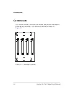
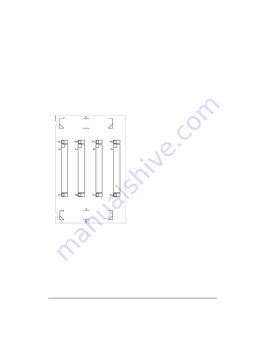
Page 22: ...Connectors 2 4 Analog 120 Pin Probing Board Manual ...

Page 23: ...20 Pin Probing Board Schematic Ref Qty Description Reference Designator Manufacturer Part Number 1 8 IDC 2X1 IDC2X1 P7 P14 FCI 90726 402HLF 2 1 0 5MM 120PIN SAMTEC_ QSH 060 F D A J1 SAMTEC QSH 060 01 F D A 3 1 0 5MM 120PIN SAMTEC_ QTH 060 F D A P1 SAMTEC QTH 060 01 F D A 4 4 IDC 15X2 SAMTEC_ TSW 115 07 L D P2 P5 SAMTEC TSW 115 07 L D ...

Page 24: ...A 2 Analog 120 Pin Probing Board Manual ...

Page 25: ...A B 4 3 2 ANALOG 12 ...

Page 26: ...9 PIN_34 PIN_37 PIN_38 PIN_41 PIN_42 PIN_45 PIN_46 PIN_49 PIN_50 PIN_53 PIN_54 PIN_57 PIN_58 PIN_59 PIN_60 PIN_61 PIN_61 PIN_62 PIN_63 PIN_63 PIN_64 PIN_65 PIN_65 PIN_66 PIN_67 PIN_67 PIN_68 PIN_69 PIN_69 PIN_70 PIN_71 PIN_71 PIN_72 PIN_73 PIN_73 PIN_74 PIN_75 PIN_75 PIN_76 PIN_77 PIN_77 PIN_78 PIN_79 PIN_79 PIN_80 PIN_81 PIN_81 PIN_82 PIN_83 PIN_83 PIN_84 PIN_85 PIN_85 PIN_86 PIN_87 PIN_87 PIN_88...

Page 27: ...s 2 2 J1 2 3 P1 2 3 P2 P5 2 3 P7 P14 2 3 contents of this probing board package 1 1 E EngineerZone xii expansion interface 1 3 I installation of board 1 2 mechanical mating details 1 3 N notation conventions xii P P1 connector 2 3 P2 P5 connector 2 3 P7 P14 connector 2 3 package contents 1 1 product overview vii R reference design information 1 4 S schematic of board B 1 system architecture of thi...

Page 28: ...Index I 2 Analog 120 Pin Probing Board Manual ...

Page 29: ... TMDXRM46CNCD DM160216 EV ADUCM350GPIOTHZ EV ADUCM350 BIO3Z ATSTK521 1130 MA160015 MA240013 MA240026 MA320014 MA330014 MA330017 TMDSCNCD28054MISO MIKROE 2152 MIKROE 2154 MIKROE 2381 TSSOP20EV MIKROE 1108 MIKROE 1516 SPS READER GEVK AC244049 AC244050 AC320004 3 2077 ATSMARTCARD XPRO EIC Q600 230 ATZB 212B XPRO SPC560PADPT100S SPC560BADPT64S MA180018 EIC Q600 220 AC164134 1 BOB 12035 BB BONE BATT 01...

Reviews: