2
dc2234af
DEMO MANUAL DC2234A
Quick start proceDure
DC2234A is easy to set up to evaluate the performance
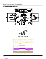
of the LT8711. Refer to Figure 3 for proper measurement
equipment setup and follow the procedure below:
NOTE: When measuring the input or output voltage ripple,
care must be taken to avoid a long ground lead on the
oscilloscope probe. See Figure 4 for the proper scope
technique.
1. Set an input power supply that is capable of 40V/12A.
Then turn off the supply.
2. With power off, connect the supply to the input termi-
nals V
IN
and GND.
3. Turn on the power at the input.
NOTE: Make sure that the input voltage never exceeds
40V.
4. Check for the proper output voltage of 12V. Turn off
the power at the input.
5. Once the proper output voltage is established, connect
a variable load capable of sinking 4A at 12V to the out-
put terminals V
OUT
and GND. Set the current for 0A.
a. If efficiency measurements are desired, an ammeter
can be put in series with the output load in order to
measure the DC2234A’s output current.
b. A voltmeter can be placed across the output terminals
in order to get an accurate output voltage measure-
ment.
6. Turn on the power at the input.
NOTE: If there is no output, temporarily disconnect the
load to make sure that the load is not set too high.
7. Once the proper output voltage is again established,
adjust the load and/or input within the operating range
and observe the output voltage regulation, ripple volt-
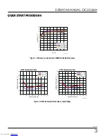
age, efficiency and other desired parameters.
8. An external clock can be added to the SYNC termi-
nal when SYNC function is used (JP1 on the SYNC
position). Please ensure that the chosen RT sets the
LT8711 switching frequency to equal or below the low-
est SYNC frequency. See the data sheet section, Clock
Synchronization.
Downloaded from
Downloaded from


