SSM2304
Rev. 0 | Page 15 of 20
EVALUATION BOARD INFORMATION
INTRODUCTION
This section describes how to configure and use the SSM2304
Evaluation Board Revision 3.0.
There are several ways to connect the audio signal to the
amplifier on the evaluation board. For example, the signal can
be connected in single-ended or differential mode, and the
output signals can be taken either after the ferrite beads or the
inductors.
BOARD DESCRIPTION
The SSM2304 evaluation board has a complete application
circuit for driving two stereo loudspeakers.
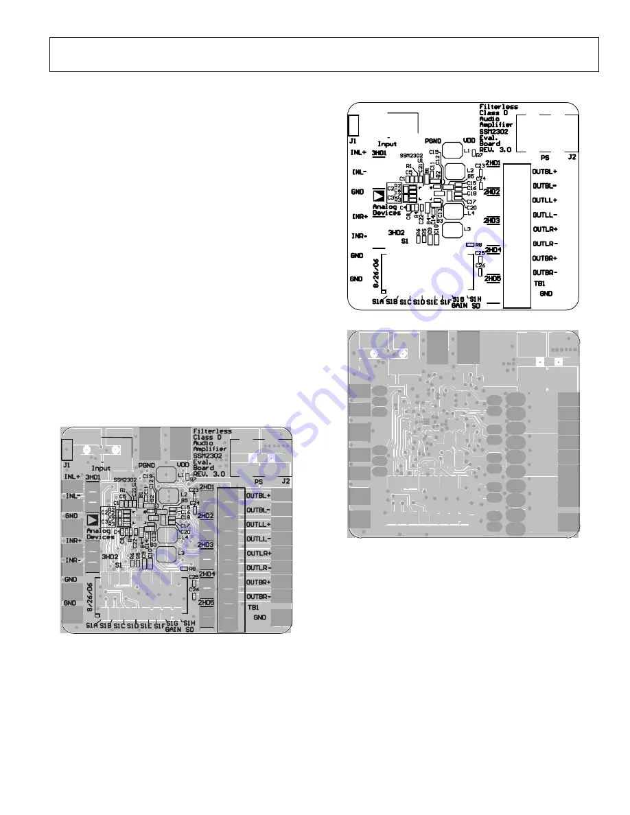
The silkscreen layer of the evaluation board is shown in Figure 41
with other top layers, including top copper, top solder mask,
and multilayer (vias).
Figure 42 shows the top silkscreen layer only. There is no
component in the bottom side; therefore, there is no bottom
silkscreen layer.
Figure 43 shows the top layers without the silkscreen layer.
Figure 44 shows the bottom layers, including bottom copper,
bottom solder mask, and multilayer (vias).
Figure 45 shows the mirrored bottom layers.
The schematic is shown in Figure 46.
06
16
2-
07
0
Figure 41. Top Silkscreen Layer with Other Top Layers
06
16
2-
0
71
Figure 42. Top Silkscreen
061
62
-0
72
Figure 43. Top Layers Without Top Screen Layer
OBSOLETE


