background image


SSM2304


Rev. 0 | Page 17 of 20 

1

2

3

J1

S

J-

3523A

OUTL

-

2

OUTL

+

1

SD

3

INL+

4

INR

+

9

NC

6

GAIN

10

IN

L-

5

IN

R

-

8

NC

7

OUTR

-

11

OUTR

+

12

VD

D

14

GN

D

13

GN

D

16

VD

D

15

PA

D

17

U1

S

S

M

2302

1

2

C7

100p

F

1 2

C8

100p

F

1

2

C5

100p

F

1

2

C6

100p

F

1

2

C2

100n

F

1

2

C1

100n

F

1

2

C4

100n

F

1

2

C3

100n

F

2

15

S1

B

10P

S

T

1

16

S1

A

10P

S

T

3

14

S1

C

10P

S

T

4

13

S1

D

10P

S

T

5

12

S1

E

10P

S

T

6

11

S1

F

10P

S

T

1

2

R3

10

0

1

2

R4

100

1

2

C9

10u

F

1

2

C10

10u

F

1

2

R2

100

1

2

R1

100

1

2

R5

20

1

2

R6

20

1

2

3

J2

P

S

_JACK

1

2

B2

BE

AD

1

2

B1

BE

AD

1

2

B4

BE

AD

1

2

B3

BE

AD

1

2

C11

1n

F

1

2

C12

1n

F

1 2

C14

1n

F

1 2

C1

3

1n

F

1

2

L1

10u

H

1

2

L2

10u

H

1

2

L3 10

u

H

1

2

L4 10u

H

1

2

C15 1u

F

1

2

C16 1u

F

1 2

C17

1u

F

1 2

C18

1u

F

1

2

3

3HD

1

3P

_HE

A

DE

R

1

2

3

3HD2

3P

_HE

A

D

E

R

1

2

C19

10

u

F

1

2

B5

BE

A

D

1

2

C20

10

u

F

2

1

4

3

6

5

8

7

10

9

TB

1

10P

_T

_B

L

O

CK

1

2

2HD1

2P

IN

A

1

2

2HD2

2P

IN

A

1

2

2HD3

2P

IN

A

1

2

2HD4

2P

IN

A

7

10

S1

G

10

PS

T

8

9

S1

H

10P

S

T

1

2

R8

100K

1

2

R7

100K

VD

D

VD

D

1

2

2HD5

2P

IN

A

1

2

C22

1n

F

1

2

C2

1

1n

F

1

IN

R

1

GN

D

1

INR+

1

IN

L

1

GN

D

1

IN

L

+

1

OU

TL

L

1

OU

TL

L+

1

O

U

T

BR+

1

OU

TB

L

+

1

OU

TB

L

1

GN

D

1

OU

TL

R

1

GN

D

1

OU

TB

R

1

OU

T

L

R

+

-

-

-

-

-

-

1

VD

D

1

PG

N

D

VD

D

1

2

C24

100

p

F

1 2

C26

100

p

F

1 2

C2

5

100p

F

1

2

C2

3

100p

F

0616

2-0

75


Figure 46. Schematic of SSM2304 Evaluation Board Rev. 3.0 


OBSOLETE

Summary of Contents for SSM2304 Series

Page 1: ...ving a 4 Ω load from a 5 0 V supply The SSM2304 features a high efficiency low noise modulation scheme It operates with 85 efficiency at 1 4 W into 8 Ω from a 5 0 V supply and has a signal to noise ratio SNR that is better than 98 dB PDM modulation is used to provide lower EMI radiated emissions compared with other Class D architectures The SSM2304 has a micropower shutdown mode with a typical shu...

Page 2: ...pical Performance Characteristics 6 Typical Application Circuits 12 Application Notes 13 Overview 13 Gain Selection 13 Pop and Click Suppression 13 EMI Noise 13 Layout 14 Input Capacitor Selection 14 Proper Power Supply Decoupling 14 Evaluation Board Information 15 Introduction 15 Board Description 15 Getting Started 18 What to Test 18 PCB Layout Guidelines 19 Outline Dimensions 20 Ordering Guide ...

Page 3: ...z VDD 3 6V 0 25 Input Common ModeVoltage Range VCM 1 0 VDD 1 V Common Mode Rejection Ratio CMRRGSM VCM 2 5 V 100 mV at 217 Hz 60 dB Channel Separation XTALK PO 100 mW f 1 kHz 78 dB Average Switching Frequency fSW 1 8 MHz Differential Output Offset Voltage VOOS 2 0 mV POWER SUPPLY Supply Voltage Range VDD Guaranteed from PSRR test 2 5 5 0 V Power Supply Rejection Ratio PSRR VDD 2 5 V to 5 0 V 70 85...

Page 4: ...se listed under Absolute Maximum Ratings may cause permanent damage to the device This is a stress rating only functional operation of the device at these or any other conditions above those indicated in the operational section of this specification is not implied Exposure to absolute maximum rating conditions for extended periods may affect device reliability THERMAL RESISTANCE θJA is specified f...

Page 5: ... Left Channel 2 OUTL Noninverting Output for Left Channel 3 SD Shutdown Input Active low digital input 4 INL Noninverting Input for Left Channel 5 INL Inverting Input for Left Channel 6 NC No Connect 7 NC No Connect 8 INR Inverting Input for Right Channel 9 INR Noninverting Input for Right Channel 10 NC No Connect 11 OUTR Noninverting Output for Right Channel 12 OUTR Inverting Output for Right Cha...

Page 6: ...UTPUT POWER W THD N 10 1 0 1 0 001 0 01 0 1 1 RL 4Ω 33µH GAIN 6dB VDD 2 5V VDD 3 6V VDD 5V 06162 021 Figure 5 THD N vs Output Power into 4 Ω AV 6 dB 100 0 001 0 01 0 00001 0 0000001 10 OUTPUT POWER W THD N 10 1 0 1 0 001 0 1 06162 004 VDD 5V VDD 2 5V RL 8Ω 33µH GAIN 6dB VDD 3 6V Figure 6 THD N vs Output Power into 8 Ω AV 6 dB 100 0 0001 20 20k FREQUENCY Hz THD N VDD 5V RL 8Ω 33µH GAIN 6dB 0 5W 0 2...

Page 7: ... 5W 10 1 0 1 0 01 0 001 100 1k 10k 06162 023 1W Figure 11 THD N vs Frequency VDD 3 6 V RL 4 Ω AV 6 dB 100 0 0001 20 20k FREQUENCY Hz THD N VDD 2 5V RL 4Ω 33µH GAIN 6dB 0 25W 0 125W 10 1 0 1 0 01 0 001 100 1k 10k 06162 024 0 5W Figure 12 THD N vs Frequency VDD 2 5 V RL 4 Ω AV 6 dB 100 0 0001 20 20k FREQUENCY Hz THD N VDD 5V RL 8Ω 33µH GAIN 18dB 0 5W 0 25W 10 1 0 1 0 01 0 001 100 1k 10k 06162 025 1W...

Page 8: ...33µH GAIN 18dB 0 5W 0 25W 10 1 0 1 0 01 0 001 100 1k 10k 06162 029 1W Figure 17 THD N vs Frequency VDD 3 6 V RL 4 Ω AV 18 dB 100 0 0001 20 20k FREQUENCY Hz THD N VDD 2 5V RL 4Ω 33µH GAIN 18dB 0 25W 0 125W 10 1 0 1 0 01 0 001 100 1k 10k 06162 041 0 5W Figure 18 THD N vs Frequency VDD 2 5 V RL 4 Ω AV 18 dB 9 0 2 5 5 5 SUPPLY VOLTAGE V SUPPLY CURRENT mA 8 7 6 5 4 3 2 1 3 0 3 5 4 0 4 5 5 0 06162 008 F...

Page 9: ...62 061 f 1kHz GAIN 18dB RL 8Ω 15µH Figure 23 Maximum Output Power vs Supply Voltage RL 8 Ω AV 18 dB 3 0 2 5 2 0 1 5 1 0 0 5 0 3 6 5 0 10 1 4 8 4 6 4 4 4 2 4 0 3 8 SUPPLY VOLTAGE V OUTPUT POWER W 06162 062 f 1kHz GAIN 18dB RL 4Ω 15µH Figure 24 Maximum Output Power vs Supply Voltage RL 4 Ω AV 18 dB 100 0 0 2 1 OUTPUT POWER W EFFICIENCY RL 4Ω 15µH 90 80 70 60 50 40 30 20 10 0 1 0 3 0 5 0 7 0 9 1 1 1 ...

Page 10: ... 2 06162 013 Figure 28 Power Dissipation vs Output Power at VDD 5 0 V RL 8 Ω 1 8 1 6 1 4 1 2 1 0 0 8 0 6 0 4 0 2 0 0 0 1 0 2 0 3 0 4 0 5 0 6 0 7 0 8 0 9 1 0 1 1 1 2 OUTPUT POWER W POWER DISSIPATION W 06162 064 VDD 3 6V RL 4Ω 15µH Figure 29 Power Dissipation vs Output Power at VDD 3 6 V RL 4 Ω Figure 30 Power Dissipation vs Output Power at VDD 5 0 V RL 8 Ω 400 0 0 1 6 OUTPUT POWER W SUPPLY CURRENT ...

Page 11: ... 70 75 80 85 SD INPUT OUTPUT 06162 018 Figure 33 Common Mode Rejection Ratio vs Frequency Figure 35 Turn On Response 0 140 10 100k FREQUENCY Hz CROSSTALK dB 100 1k 10k 20 40 60 80 100 120 VDD 3 6V VRIPPLE 1V rms RL 8Ω 33µH 06162 017 7 2 20 180 TIME ms VOLTAGE 6 5 4 3 2 1 0 1 0 20 40 60 80 100 120 140 160 SD INPUT OUTPUT 06162 019 Figure 34 Crosstalk vs Frequency Figure 36 Turn Off Response O B S O...

Page 12: ... 2 22nF1 22nF1 22nF1 LEFT IN LEFT IN RIGHT IN RIGHT IN SSM2304 Rext Rext Rext Rext 0 1µF VBATT 2 5V TO 5 0V 10µF 06162 030 Figure 37 Stereo Differential Input Configuration FET DRIVER MODULATOR VDD VDD GND GND INTERNAL OSCILLATOR OUTR OUTR OUTL OUTL BIAS FET DRIVER MODULATOR INR INR SD SHUTDOWN INL INL 22nF 22nF 22nF 22nF LEFT IN RIGHT IN SSM2304 0 1µF VBATT 2 5V TO 5 0V 10µF 06162 031 Rext Rext R...

Page 13: ...o amplifiers can occur when shutdown is activated or deactivated Voltage transients as low as 10 mV can be heard as an audio pop in the speaker Clicks and pops can also be classified as undesirable audible transients generated by the amplifier system therefore as not coming from the system input signal Such transients can be generated when the amplifier system changes its operating mode For exampl...

Page 14: ...ital ground and power planes the analog ground plane should be underneath the analog power plane and similarly the digital ground plane should be underneath the digital power plane There should be no overlap between analog and digital ground planes nor analog and digital power planes INPUT CAPACITOR SELECTION The SSM2304 will not require input coupling capacitors if the input signal is biased from...

Page 15: ...two stereo loudspeakers The silkscreen layer of the evaluation board is shown in Figure 41 with other top layers including top copper top solder mask and multilayer vias Figure 42 shows the top silkscreen layer only There is no component in the bottom side therefore there is no bottom silkscreen layer Figure 43 shows the top layers without the silkscreen layer Figure 44 shows the bottom layers inc...

Page 16: ...r the SSM2304 S1H controls the shutdown function The upper position shuts down the amplifier and the lower position turns on the amplifier The upper right corner has a dc power jack connector The center pin is for the positive terminal It is compatible with 3 V to 5 V voltage and the maximum peak current is approximately 1 2 A when driving a 4 Ω load for SSM2304 only and 0 6 A when driving an 8 Ω ...

Page 17: ...EAD 1 2 B3 BEAD 1 2 C11 1nF 1 2 C12 1nF 1 2 C14 1nF 1 2 C13 1nF 1 2 L1 10uH 1 2 L2 10uH 1 2 L3 10uH 1 2 L4 10uH 1 2 C15 1uF 1 2 C16 1uF 1 2 C17 1uF 1 2 C18 1uF 1 2 3 3HD1 3P_HEADER 1 2 3 3HD2 3P_HEADER 1 2 C19 10uF 1 2 B5 BEAD 1 2 C20 10uF 2 1 4 3 6 5 8 7 10 9 TB1 10P_T_BLOCK 1 2 2HD1 2PINA 1 2 2HD2 2PINA 1 2 2HD3 2PINA 1 2 2HD4 2PINA 7 10 S1G 10PST 8 9 S1H 10PST 1 2 R8 100K 1 2 R7 100K VDD VDD 1 ...

Page 18: ...ng needed for an 8 Ω load is about 600 mA and the impedance for 100 MHz must be greater than 600 Ω In addition the lower the DCR dc resistance of these beads the better for minimizing their power consumptions The recommended bead is described in Table 6 4 Output shunting capacitors for the beads There are two groups of these capacitors C11 C12 C13 and C14 and C23 C24 C25 and C26 The former is for ...

Page 19: ...ip as possible and connect its ground terminal to the PCB ground area containing the power supply traces 6 Place B5 the bead for the power supply as close to the amplifier chip as possible keeping it on the same side of the PCB as the chip 7 The ferrite beads can block an EMI of up to 160 MHz in frequency To eliminate EMIs greater than the 160 MHz place a small capacitor such as 100 pF in parallel...

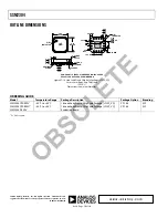
Page 20: ...N Figure 47 16 Lead Lead Frame Chip Scale Package LFCSP_VQ 3 mm 3 mm Body Very Thin Quad CP 16 3 Dimensions shown in millimeters ORDERING GUIDE Model Temperature Range Package Description Package Option Branding SSM2304CPZ REEL 40 C to 85 C 16 Lead Lead Frame Chip Scale Package LFCSP_VQ CP 16 3 A1F 1 SSM2304CPZ REEL7 40 C to 85 C 16 Lead Lead Frame Chip Scale Package LFCSP_VQ CP 16 3 A1F 1 SSM2304...

Reviews: