DBS9900 User’s Manual
DBS9900 Preparation & Installation
2-5
82-28993 Revision 01
2.5.3
A16, A24 and A32 Communications Mode
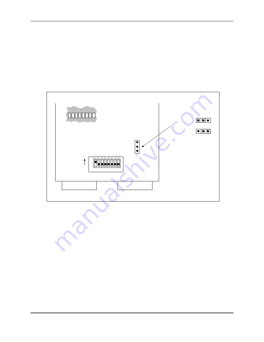
The DBS9900 contains jumpers that can be set for A24 or A32 Communications Mode. These
jumpers are configured at the factory for A24 mode. To operate in A16 mode, do not set any
jumpers.
In order to change this setting the DBS9900 boards must be removed from their case to access
the jumpers. Proceed with caution.
Use the figure below to determine jumper location when setting the jumpers for A24 or A32
Communications Mode.
Note: A24 is only recommended when using a GPIB-VXI-C VXI controller.
P2
P1
1 2
3 4
5 6 7
8
A13 A12 A11 A10
A9 A8 A7 A6
S1
Note: S1 is shown enlarged
for presentation purposes.
DBS9900 Rear
ON
The switches must be set through
these holes on the case using a
needle probe (or a similar tool).
The dip switch is shown below.
1
2
3
A24/A32 Jumper Settings
3
2
1
3
2
1
A24 (short pin 2 to 3)
A32 (short pin 1 to 2)
Logical Address Dip Switch
Figure 2-3 Jumper Settings for A24 and A32 Communications Mode
Artisan Technology Group - Quality Instrumentation ... Guaranteed | (888) 88-SOURCE | www.artisantg.com


