DBS9900 User’s Manual
iv
DBS9900 User’s Manual
82-28993 Revision 01
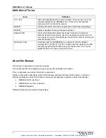
Definition of Terms
Term
Definition
I/0 1, I/0 2
Also called daughterboards, and/or modules. There can be one or two
modules installed in the DBS9900. I/O 1 refers to the first installed
module and I/O 2 refers to the second.
DBS901
Arbitrary Waveform Generator daughterboard (purchased separately).
DBS902
Digitizer daughter board (purchased separately).
Sample Clock
Clock which drives the sample rate of each module. An
Internal
or
External
Sample Clock may be used. It is possible (using the driver) for
one module to use an Internal Sample Clock and the other to be using an
External Sample Clock.
Reference Clock
Timebase used by the DBS9900 as a reference for both installed
modules (I/O 1 and I/O 2). This PLL 10MHz reference signal is provided
internally by default but an
External
signal may be used. Can only be
applied to the CLK 2 input on the Front Panel.
About this Manual
This manual is organized in a top-down manner.
This means that the first chapters provide overview and installation information.
Then, configuration and setup information is presented.
Finally, functionality is described. Each of the following sections describe similar content – but from a
high-level perspective (Soft Front Panel) to a low-level perspective (hardware register descriptions).
•
DBS9900 Soft Front Panel
•
DBS9900 Driver (.DLL) Functions
•
DBS9900 Registers
Reference material is presented in Appendices.
Artisan Technology Group - Quality Instrumentation ... Guaranteed | (888) 88-SOURCE | www.artisantg.com


