AMD2000 Series D2xxx Servo Drive - User Guide
28
D-000088 Rev 10
ANCA Motion
6
Power Wiring
6.1
What this Chapter Contains
This chapter contains information related to connecting the drive electrically to the incoming mains, motor and
brake as well as what to be mindful of such as:
Checking Assembly Insulation
Cable Connection and Earthing
Power Conditioning
Regenerative Brake Selection / Calculation
6.2
Checking the Insulation of the Assembly
Installed supply and motor cables must be tested for functioning insulation according to local regulations by using
an insulation resistance tester at 500V.
The AMD2000 drive has input supply voltage surge suppression components fitted to protect the drive from line
voltage transients typically originating from lightning strikes or switching of high power equipment on the same
supply. When carrying out a HiPot (Flash or megger) test on an installation in which the drive is fitted, the voltage
surge suppression components may cause the test to fail and potentially damage the drive. To accommodate this
type of system HiPot test, the cables
must
be disconnected from the drive.
The cables to be disconnected and tested are: control voltage single phase supply (L1C/L2C), single-phase or
three-phase supply (L1/L2/L3), inductor connector (P1/P2), brake resistor connector (P/C/D) and motor connector
(U/V/W).
6.3
Mains Power Supply
The following components are required for connection to the mains supply:
Isolation switch to allow correct isolation of the system from the power supply
Circuit breakers to protect cables, filter and drive
EMI filter and line reactor to limit EMI on the mains supply
The mains control supply (LC1, LC2) for the drive requires a single phase supply which can be either two phases
from a 3 phase supply (100-240V line to line) or from a dedicated single phase supply (100-240V line to neutral).
The mains power supply (L1, L2, L3) can be either from two or three phases of a 3-phase supply (100-240V line
to line) or a single phase supply (100-240V line to neutral).
The mains control supply can be linked to the mains power supply allowing power to be applied at the same time.
External soft start circuitry is optional, refer to
6.6 Power Supply Soft Start Module
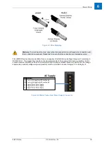
mains and control supply cables are terminated on the 10
-
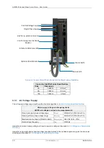
Recommended strip length for wires into cage clamp style (push in spring type) connectors is 10mm. Note that
these cage clamp connectors must be used with stranded wire without the use of ferrules. Acceptable lead dress
is illustrated in
The EMI filter and line reactor are required for EMC compliance; refer to
6.5 Installations conforming to the EMC
for details on the recommended EMC compliant installation.
Summary of Contents for AMD2000 Series
Page 1: ...AMD2000 Series D2xxx Servo Drive User Guide D 000088 Rev 10 ...
Page 131: ...Technical Data ANCA Motion D 000088 Rev 09 119 10 ...
Page 132: ...AMD2000 Series D2xxx Servo Drive User Guide 120 D 000088 Rev 10 ANCA Motion 10 9 1 2 3 Phase ...
Page 133: ...Technical Data ANCA Motion D 000088 Rev 09 121 10 ...
Page 135: ...Technical Data ANCA Motion D 000088 Rev 09 123 10 ...
Page 136: ...AMD2000 Series D2xxx Servo Drive User Guide 124 D 000088 Rev 10 ANCA Motion 10 9 2 2 3 Phase ...
Page 137: ...Technical Data ANCA Motion D 000088 Rev 09 125 10 ...
Page 139: ...Technical Data ANCA Motion D 000088 Rev 09 127 10 ...
Page 140: ...AMD2000 Series D2xxx Servo Drive User Guide 128 D 000088 Rev 10 ANCA Motion ...
Page 141: ...Technical Data ANCA Motion D 000088 Rev 09 129 10 10 9 3 2 3 Phase ...
Page 142: ...AMD2000 Series D2xxx Servo Drive User Guide 130 D 000088 Rev 10 ANCA Motion ...


