Power Wiring
ANCA Motion
D-000088 Rev 09
45
6
6.8.2 Motor Power Cable Installation
6.8.2.1
Cable Shielding
In order to comply with the EMC requirements and minimize effects to other equipment, motor cables and power
supply cables from line filter AMD2000 drive must be used with shields. The cable shield minimizes
electromagnetic noise which may be coupled into nearby conductors, and the shield provides a low impedance
path for common mode noise currents back to the drive via EMC filter or drive common mode capacitors.
6-14 Motor connections and shielding
which illustrates the path of common currents. The gear tray layout and
correct bonding of the shield in the cabinet is a critical component in managing EMC problems. The following
guidelines must be followed.
Cables between the inverter and motor must be shielded, and the shield grounded at both ends.
Use motor cables with dedicated PE conductor(s). Do not use the shield as a PE.
The shield clamping surface must be free of paint.
Use specifically designed shield clamps. Do not use plastic ties.
Select shield connections with low impedance in the MHz range.
Shield clamps can be with or without mechanical strain relief
Metallic components in the gear tray and cabinet must have a large surface area and should be
connected to one another with a high level of RF conductivity.
6.8.2.1.1
D2103 Cable Shielding
Use an Armature Bracket in order to terminate the shielded cable assembly.
The Armature Termination Bracket assembly consists of the following parts:
Armature Termination Bracket
EMC Saddle Clamp
3 x M4 screws
1 x M6 screw
Shield for bracket ordering details.
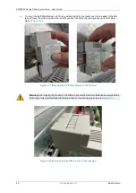
Clamp the Armature Termination Bracket down as shown below using the 2 x M4 existing screws that
came with the drive. Maximum tightening torque is 2.5Nm.
Carefully remove the Armature cable sheath to expose the metal braid. Expose approximately 25mm of
braid length. Refer to
section 6.8.2.1.4
for details on this process and suggested tools.
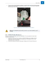
The position of the exposed braid is to coincide with the EMC Saddle Clamp and the metal bracket as
shown below in order to provide sufficient contact for termination.
Tighten the Saddle Clamp screw to 0.5Nm.
Fit the armature plug into the armature connector on the drive.
Ensure that the Armature Cable Earth wire is connected to an M4 ring lug using one M4 screw from the
Armature Termination Bracket assembly kit, and connect to the bracket as shown below. Maximum
tightening torque is 1.5Nm.
The Armature Termination Bracket has been designed to allow the Protective Earth (PE) wires to be
connected in two ways.
a)
Connection for two PE wires less than 10mm² Cu by using two M4 screws.
Maximum tightening torque is 1.5 Nm.
b)
A single PE wire if the conductor size is greater than 10mm² Cu by using a single M6 screw.
Maximum tightening torque is 3 Nm.
Summary of Contents for AMD2000 Series
Page 1: ...AMD2000 Series D2xxx Servo Drive User Guide D 000088 Rev 10 ...
Page 131: ...Technical Data ANCA Motion D 000088 Rev 09 119 10 ...
Page 132: ...AMD2000 Series D2xxx Servo Drive User Guide 120 D 000088 Rev 10 ANCA Motion 10 9 1 2 3 Phase ...
Page 133: ...Technical Data ANCA Motion D 000088 Rev 09 121 10 ...
Page 135: ...Technical Data ANCA Motion D 000088 Rev 09 123 10 ...
Page 136: ...AMD2000 Series D2xxx Servo Drive User Guide 124 D 000088 Rev 10 ANCA Motion 10 9 2 2 3 Phase ...
Page 137: ...Technical Data ANCA Motion D 000088 Rev 09 125 10 ...
Page 139: ...Technical Data ANCA Motion D 000088 Rev 09 127 10 ...
Page 140: ...AMD2000 Series D2xxx Servo Drive User Guide 128 D 000088 Rev 10 ANCA Motion ...
Page 141: ...Technical Data ANCA Motion D 000088 Rev 09 129 10 10 9 3 2 3 Phase ...
Page 142: ...AMD2000 Series D2xxx Servo Drive User Guide 130 D 000088 Rev 10 ANCA Motion ...

