Control Wiring
ANCA Motion
D-000088 Rev 09
63
7
7.4
Analogue I/O
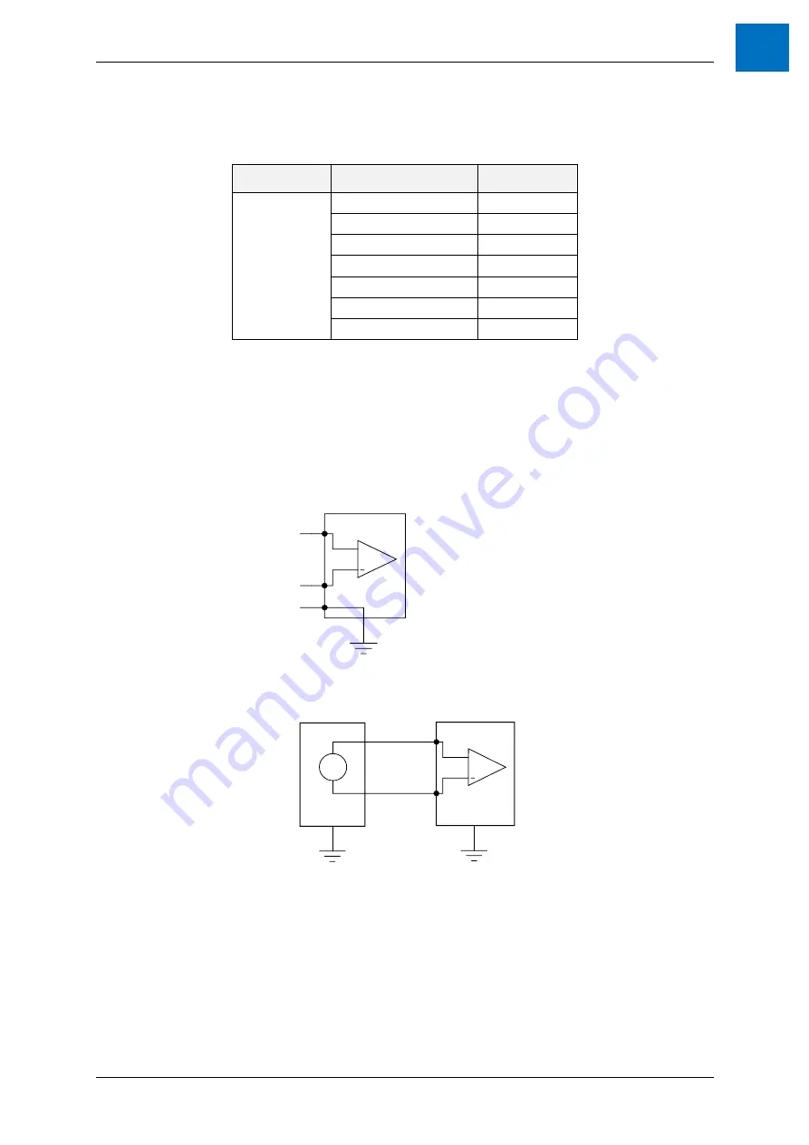
All analogue Input and Output signals are connected to the drive via X4 with the following pins,
Connector
Pin Number
Label
X4
or
I/O Module
1
AI-01+
26
AI-01-
2
AI-02+
27
AI-02-
28
AO-01
29
AO-02
3, 4, 30, 31
AGND
for detailed specifications
7.4.1 Analogue Inputs
The analogue inputs pass through a differential buffer and second order low-pass filter with a cut-off frequency of
approximately 700 Hz.
7.4.1.1
Idealised drawing of Analogue Input Circuit
+
AMD2000
AI+
AI-
AGND
7.4.1.2
Typical Connection Examples of Analogue Input
Vs
+
Signal source
AMD2000
AI-XX+
AI-XX-
Figure 7-3 Typical Example of Floating Differential Input Connection
Summary of Contents for AMD2000 Series
Page 1: ...AMD2000 Series D2xxx Servo Drive User Guide D 000088 Rev 10 ...
Page 131: ...Technical Data ANCA Motion D 000088 Rev 09 119 10 ...
Page 132: ...AMD2000 Series D2xxx Servo Drive User Guide 120 D 000088 Rev 10 ANCA Motion 10 9 1 2 3 Phase ...
Page 133: ...Technical Data ANCA Motion D 000088 Rev 09 121 10 ...
Page 135: ...Technical Data ANCA Motion D 000088 Rev 09 123 10 ...
Page 136: ...AMD2000 Series D2xxx Servo Drive User Guide 124 D 000088 Rev 10 ANCA Motion 10 9 2 2 3 Phase ...
Page 137: ...Technical Data ANCA Motion D 000088 Rev 09 125 10 ...
Page 139: ...Technical Data ANCA Motion D 000088 Rev 09 127 10 ...
Page 140: ...AMD2000 Series D2xxx Servo Drive User Guide 128 D 000088 Rev 10 ANCA Motion ...
Page 141: ...Technical Data ANCA Motion D 000088 Rev 09 129 10 10 9 3 2 3 Phase ...
Page 142: ...AMD2000 Series D2xxx Servo Drive User Guide 130 D 000088 Rev 10 ANCA Motion ...


