AMD2000 Series D2xxx Servo Drive - User Guide
34
D-000088 Rev 10
ANCA Motion
6.5
Installations conforming to the EMC Directive
EMC stands for Electromagnetic compatibility. It is the ability of electrical/electronic equipment to operate without
problems within an electromagnetic environment. The equipment must not disturb or interfere with any other
product or system within its locality. Variable speed drives are a source of interference, and all parts which are in
electrical or airborne connection within the power drive system (PDS) are part of the EMC compliance.
The drive interference is generated from the output voltage waveform which is a rapidly changing voltage
waveform (Pulse Width Modulation). The voltage transitions present on all motor cables and motor windings
induce parasitic common mode currents (I
LEAK
) in the stray capacitance of the motor and cable system. See
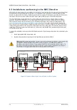
Figure 6-5 Common Mode Noise Current Paths in a Drive System.
The common mode currents return to the
drive inverter by the lowest available impedance paths which must be carefully managed to prevent interference
voltages being generated in other equipment connected to the same earth system. The internal common mode
capacitors of the drive provide one return path (I
DC
) to the drive, and the EMI filter provides another return path
via the drive mains input.
To ensure the installation conforms to the EMC Directives, both of the following actions must be completed by the
installer;
1. Select appropriate EMC components, and
2. Implement appropriate wiring setups to limit high-frequency harmonic effects.
Warning:
EMC related performance, however, can still be influenced by factors not covered by the
configuration details supplied in this section of the user guide. It is difficult to consider all
necessary wiring and conditions of the equipment particular to all possible customer needs. For
this reason, the EMC conformance of the system as a whole must be confirmed by customer in
accordance to the appropriate standards for their application and market.
IGBT Inverter
Line Filter
AMD2000
Motor Cable
I
leak
PE terminal and metal gear tray ground
PE
I
PCC
Converter Cabinet
LF
I
DC
I
Heats ink
Line Reactor
Figure 6-5 Common Mode Noise Current Paths in a Drive System
Summary of Contents for AMD2000 Series
Page 1: ...AMD2000 Series D2xxx Servo Drive User Guide D 000088 Rev 10 ...
Page 131: ...Technical Data ANCA Motion D 000088 Rev 09 119 10 ...
Page 132: ...AMD2000 Series D2xxx Servo Drive User Guide 120 D 000088 Rev 10 ANCA Motion 10 9 1 2 3 Phase ...
Page 133: ...Technical Data ANCA Motion D 000088 Rev 09 121 10 ...
Page 135: ...Technical Data ANCA Motion D 000088 Rev 09 123 10 ...
Page 136: ...AMD2000 Series D2xxx Servo Drive User Guide 124 D 000088 Rev 10 ANCA Motion 10 9 2 2 3 Phase ...
Page 137: ...Technical Data ANCA Motion D 000088 Rev 09 125 10 ...
Page 139: ...Technical Data ANCA Motion D 000088 Rev 09 127 10 ...
Page 140: ...AMD2000 Series D2xxx Servo Drive User Guide 128 D 000088 Rev 10 ANCA Motion ...
Page 141: ...Technical Data ANCA Motion D 000088 Rev 09 129 10 10 9 3 2 3 Phase ...
Page 142: ...AMD2000 Series D2xxx Servo Drive User Guide 130 D 000088 Rev 10 ANCA Motion ...


