Product Overview
ANCA Motion
D-000129 Rev 09
11
3
3.4
Operating Principle
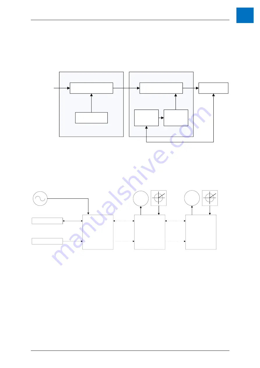
The simplified diagram of the AMD5x control is shown below. The 3 phase AC supply voltage is converted to DC,
which is then distributed via a bus to each Drive. The number of drives is chosen by the customer. Each drive
converts the DC into the required variable frequency AC voltage signal to drive each motor.
AC Motor
DC Control
Switching
Control
3 Phase
AC Input
DC/AC Converter
AC/DC Converter
Drive
Control
AMD5x PIU
AMD5x DRIVE
Figure 3-1: AMD5x PIU and Drive operating principle
3.5
System Overview
The AMD5x system comprises one PIU, and one or more digital servo drives as shown in the following figure:
PIU
DRIVE 1
Control Master
380-480VAC (3Φ+E)
Power Supply
M
24V
EtherCAT
DC BUS
DRIVE n
EtherCAT
DC BUS
M
EtherCAT
Figure 3-2: AMD5x PIU and Drive system overview
Above example is of a PIU and Drive system supplied from 3 phase mains connection and 24 Vdc supply. Motion
control commands are received from a control master system, such as a CNC in the form of structured position
commands.
Summary of Contents for AMD5x Series
Page 12: ......


