26
4.2.3 Insert tension bars into tension pocket at bottom of gable end. Insert tension bar connector between tension bars
and through tension strap loop. Insert tension bar corner connectors at corners. See
Figure 4.2c.
Tension fab-
ric until it is tight. Make sure the bottom pocket line on ends are level. Add and/or release tension as necessary
to adjust.
4.2.4 Repeat steps 4.2.1 thru 4.2.3 for opposite gable end.
4.2.5 Gable Ends are installed.
4.2.6
Now Tension all cables fully.
4.3 Installing Optional Fabric Walls:
Use drop cloths (not included) and ladders to assist installation. Walls are
made in two pieces with FR/Warning labels on the inside, ground rail pockets on the outside.
NOTE
: Gable end wing
walls are used at outer bays of the gable ends and there are right and left versions. Mid walls are used at center gable
end bays and at all mid bays.
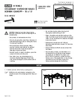
4.3.1 Start installing unlaced walls by inserting top of kedar into outside channel opening and slide upper portion of wall
to top of upright. Then insert bottom of kedar into channel opening and slide kedar down to bottom of upright.
Gather wall toward upright and start inserting wall tabs into channel of eave purlins.
IMPORTANT:
Gable end wall
tabs insert into Outer Channel of the eave purlins and Mid wall tabs insert into Inner Channel.
4.3.2 After all tabs are inserted, walls may be laced from top to bottom. Tie off bottom long loop.
4.3.3 Insert Ground Rails into bottom pocket of all mid walls and secure to base plate L-Pins at all mid uprights as shown
in
Figure 4.3a.
4.3.4 Insert Ground Rails into top pockets of all gable end walls and secure to end of cable bracing eyebolt at base of
gable end corner upright
(Fig. 4.3a)
and to Gable End Base Plate L-Pin.
Figure 4.1a
Figure 4.2a


