PRODUCT MANUAL
68/72ST Above Deck Compact Motor
™
10
STEP 4
Install motor unit.
Having a second person to assist during this step may help to avoid fouling the wiring and drain tube with sealant as they are
passed through the deck.
4.1 Apply sealant to the deck to prevent water ingress. In addition to sealing the mounting holes, apply a bead of sealant
around the perimeter of the base to form a completely watertight seal.
NOTE: For mounting on metal surfaces, the base must also be completely isolated from the mounting surface to prevent
galvanic corrosion.
4.2 Fit the motor unit [1] to the deck using the appropriate length ISO 4017-A4 M10 or 3/8” bolts, large washers or backing
plate, and locking nuts.
4.3 Place the stainless steel cover [2] back on the motor unit and slide it down into position.
STEP 5
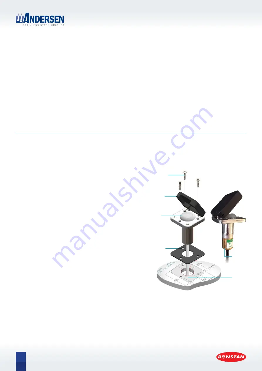
Install push buttons
The push buttons [A1] require 50mm clearance depth below the
mounting surface. They are supplied with a short 190mm (7 1/2”)
cable lead; each is connected below deck to a 1000mm (39”) long
control cable [A12] and then to one of the short cable leads from the
motor. Extension cables are available and may be ordered separately
if necessary.
5.1 Select the desired location. For safety reasons it is recommended
that the push buttons [A1] are located in close proximity to the
winch, preferably within reach.
5.2 Determine the preferred orientation of the hinged covers (on
vertical surfaces it should open upwards). Then using the drilling
template or the rubber gasket [A2] as a guide, drill a Ø25mm (1”)
hole.
5.3 Drill a 3mm (1/8”) hole in each of the mounting screw locations.
5.4 Fit gaskets and push buttons in place. Secure the push button
units with the M4x20mm self tapping screws [A10], using a small
amount of sealant at each hole.
5.5 Ensure that the breather channel on the side of the through-deck
tube of the push button is clear and free of dirt or sealant.
Breather
channel
Drilling
template
Mounting
screws
Hinged
cover
Push
button
Rubber
gasket
Push button installation


