


Bulletin II-102051-EN • Revision B
November-2007
11
!!
.
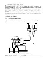
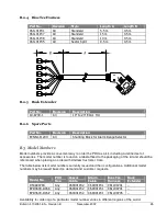
Select the installation location. The PDU installs in a standard 19” rack (or 23” rack using a Rack
Extender) in a climate controlled environment. It can be mounted in any orientation. Ensure optimum
airflow around the instrument for cool operation and maximum life expectancy.
Inspect the equipment. Ensure that all items are present, of the correct description, and without
evident damage.
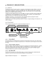
Locate connection points for supply power, alarm interface, and Bias Tees. Determine the routing of
cables. Verify that the supplied cables are sufficient to reach these points. If not, relocate the PDU or
obtain cables of alternate length or style.
.
0
The following tools and supplies may be required to complete the installation:
•
Rack screws and screwdriver
•
Needle-nose pliers (if repositioning the Alarm Range Selector)
•
Ground cable with terminals, fasteners, wrench (10 mm), and other required tools
•
Terminals for Power and Alarm Cables, wire stripper, and other required tools
•
Fuse or circuit breaker for BTS power panel (1 – 5 A recommended)
•
Torque wrench, 7 – 10 in-lbs (0.8 – 1.1 Nm), 8 mm or 5/16”
•
Weather-sealing materials (for Bias Tee connections if outdoors)
•
Cable ties and marking materials
.
6
,:
4
Determine the applicable alarm current range based on the type of TMA used. See the table below
for supported TMA current consumption ranges.
' (
) *
&
+
* &
& '
2 3 ./4
5.
6.74
8 '
.4 3 2 .
5.
62 2
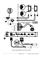
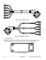
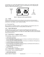
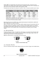
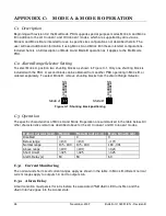
Verify that the shunting block is correctly positioned in the Alarm Range Selector on the rear panel of
the PDU (Figure 12). To reposition, pull out the shunting block using needle-nose pliers and reinsert
it in the desired position.
LO CURRENT MODE
HI CURRENT MODE
ALARM RANGE
SELECTOR
LO
C
U
R
R
E
N
T
H
I
C
U
R
R
E
N
T
Figure 12: Alarm Range Selector
Summary of Contents for Multimode Power Distribution Unit
Page 1: ...Installation and Operation User Guide...
Page 2: ......
Page 4: ...iv November 2007 Bulletin II 102051 EN Revision B 0 1...
Page 31: ......