Bulletin II-102051-EN • Revision B
November-2007
13
%
) *,
%
"
-"
.
%
&-"
.
.
"
9
:
:7 ;! <
= '
'
>$
= '
'
%
9
?
?7 ;! <
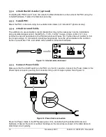
Use a dedicated circuit for the PDU if the BTS power panel is so equipped. Install a fuse or circuit
breaker with a rating in the 1-5 A range.
"
6
,:
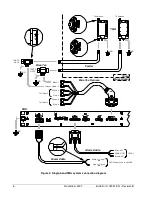
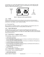
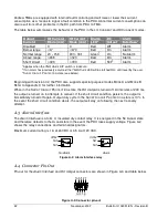
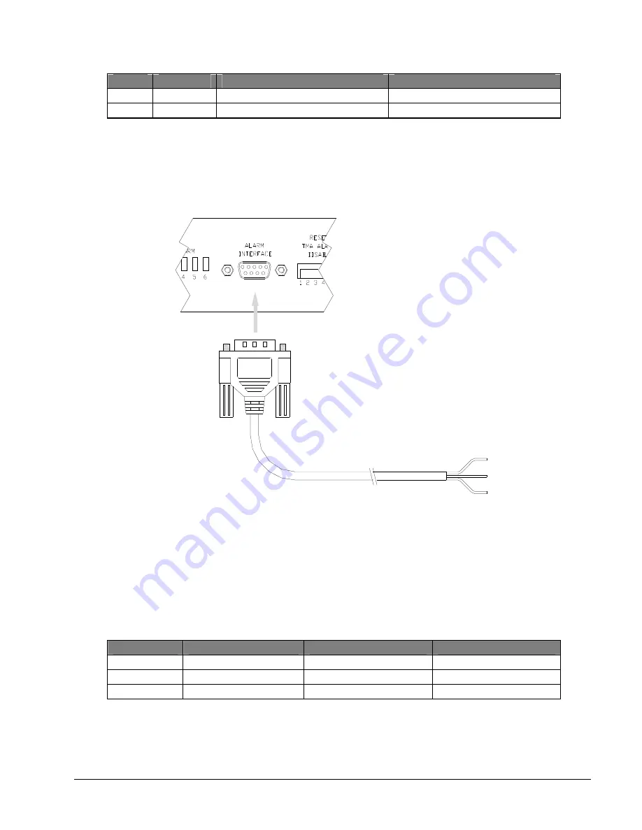
Connect the Alarm Cable to the Alarm Interface connector and tighten the jackscrews (Figure 15).
Figure 15: Alarm Cable connection
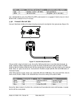
Choose which relay terminals to use. Using the NO relay terminal is recommended because an
alarm indication will be obtained also in case the Alarm Cable becomes disconnected. The BTS
External Alarm Interface (EAI) should then be programmed to expect a closed circuit and to indicate
alarm when an open circuit occurs. Connection to the EAI is made with the NO and COM wires of
the Alarm Cable.
If the EAI expects an open circuit, use instead the NC and COM wires. The circuit will then close in
the A
LARM
condition. Refer to the table below for the color coding of the Alarm Cable.
%
.
*
) +
*
+
*
>$
&
'
'
#
&
&
'
&
&
&
Route the Alarm Cable to the EAI, trim, and attach with suitable terminals and hardware. Insulate
and tie off the unused wire.
Summary of Contents for Multimode Power Distribution Unit
Page 1: ...Installation and Operation User Guide...
Page 2: ......
Page 4: ...iv November 2007 Bulletin II 102051 EN Revision B 0 1...
Page 31: ......

