14
November-2007
Bulletin II-102051-EN • Revision B
6 #+
$ ,
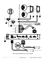
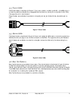
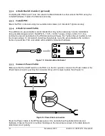
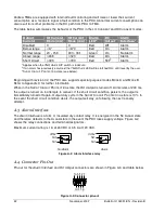
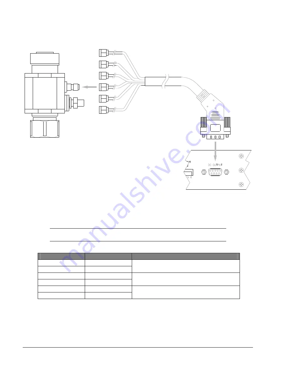
Connect the Bias Tee Harness to the DC Output connector and tighten the jackscrews (Figure 16).
Figure 16: Bias Tee Harness connection
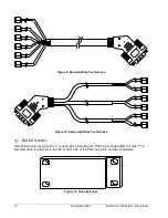
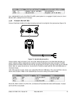
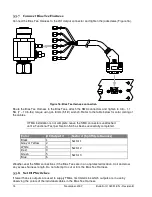
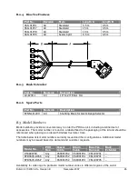
Route the Bias Tee Harness to the Bias Tees, attach the SMA connectors and tighten to 0.8 – 1.1
Nm (7 – 10 in-lbs) torque using an 8 mm (5/16”) wrench. Refer to the table below for color coding of
the cables.
If TMA installation is not complete, leave the SMA connectors unattached
until a Functional Test per Section 5.4 has been successfully completed.
%
#%/
0
0
. 1
"
"
1
.
=
@
#
.
>$
2
A
=
/
'
7
2
Weather-seal the SMA connections if the Bias Tees are in an unprotected location. Coil and stow
any excess harness length. Do not attempt to cut or trim the Bias Tee Harness.
;
3+68
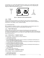
If fewer than six outputs are used to supply TMAs, first determine which outputs are in use by
observing the colors of the individual cables in the Bias Tee Harness.
Summary of Contents for Multimode Power Distribution Unit
Page 1: ...Installation and Operation User Guide...
Page 2: ......
Page 4: ...iv November 2007 Bulletin II 102051 EN Revision B 0 1...
Page 31: ......

