background image

24 

November-2007 

Bulletin II-102051-EN • Revision B 

' #(


#

,


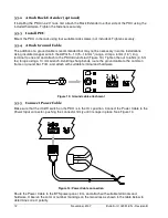
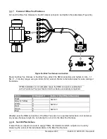
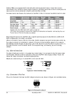
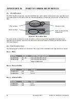
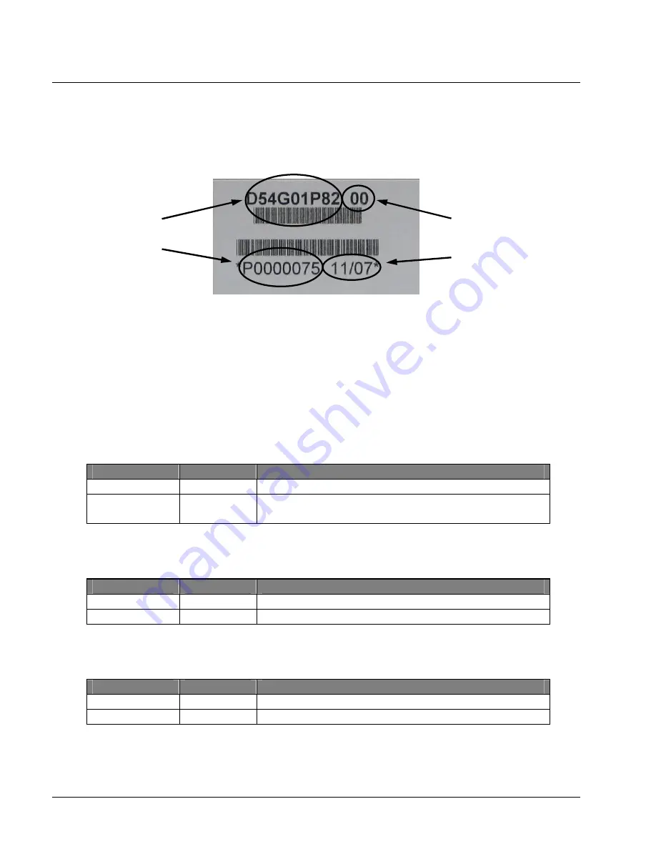
The PDU and its accessories are each identified by a part number and revision code, typically found 

on a label affixed to the item and/or its individual packaging. A label as in Figure B-1 is affixed to the 

PDU. 


Figure B-1: Part number label 

The part number and revision code should be verified to ensure the applicable Installation and 

Operation User Guide is used and should also be referenced when contacting Andrew Customer 

Technical Support. 

,


8 "

6

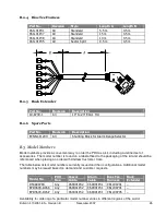
The following part numbers are included in the scope of this Installation and Operation User Guide: 

#


5

) -

  !"

+

*   & "

(

!/A= ."4

? .

& '

C8 '

!/A= ."4

& '

C8 '

C


#


3 ,


5

) -

  !"

3 &

7.

."2

/

7.

."24

./


#


,:


5

) -

  !"

3 &

7.

."2.

7.

."2

./


Part number 

Revision code 

Serial number 

Date of manufacture 

Week/Year 

Summary of Contents for Multimode Power Distribution Unit

Page 1: ...Installation and Operation User Guide...

Page 2: ......

Page 3: ...9 4 7 Rack Extender 10 5 1 Preparation 11 5 2 Tools and Supplies 11 5 3 Installation Procedure 11 5 4 Functional Test 15 6 1 Start Up 17 6 2 Voltage Regulation 17 6 3 Current Monitoring 17 6 4 Short C...

Page 4: ...iv November 2007 Bulletin II 102051 EN Revision B 0 1...

Page 5: ...ription section the user is acquainted with the external features of the PDU and its accessories as they are identified and their functions described The Installation section provides all necessary in...

Page 6: ...available short circuit currents Unintentional short circuits can cause dangerous heating fire or equipment damage Turn off circuit breakers or remove fuses when work is performed on the power supply...

Page 7: ...sector illustrations of several RF path configuration examples While frequency bands vary and variations can occur the examples provide guidance for many common situations Contact your Andrew Corpora...

Page 8: ...be present in the other branch either integral to the diplexers or in external devices as shown 1 0 In Figure 2 dual band diplexed Andrew OneBase TMAs are used with shared feeders and shared antennas...

Page 9: ...eceives DC input power from the BTS and outputs a summary alarm signal to the BTS The Bias Tee Harness is connected from the PDU to up to six Bias Tees to provide 12 VDC power to the TMAs via the feed...

Page 10: ...to 60 VDC Blue 6 Green 5 Red 4 White 3 To Sector 3 To Sector 2 Gray or Yellow 2 Black 1 To BTS RX TX To BTS RX TX To Antenna To Antenna A N T TMA Bias Tee Bias Tee Harness PDU Power Cable Alarm Cable...

Page 11: ...wer for the PDU is provided by the BTS Positive or negative voltage in the range 20 60 VDC is accepted The front panel connections and controls are illustrated in Figure 5 Figure 5 Front panel 5 0 5 0...

Page 12: ...no supply power to the PDU the default indication is the ALARM state An insulated relay is used as the Alarm Interface 3 6 8 Flip down to ENABLE current monitoring for each output Flip up to DISABLE...

Page 13: ...D sub plug on one end for connection to the PDU The opposite end is unterminated Alarm Cables are available in a selection of lengths and can be trimmed to the desired length on site Figure 8 Alarm C...

Page 14: ...ias Tee Harness Figure 10 Sector split Bias Tee Harness 1 2 3 A Rack Extender see Figure 11 is used when installing the PDU in a standard EIA 23 rack The extender plate is attached to the left or righ...

Page 15: ...ck screws and screwdriver Needle nose pliers if repositioning the Alarm Range Selector Ground cable with terminals fasteners wrench 10 mm and other required tools Terminals for Power and Alarm Cables...

Page 16: ...ttach to the PDU Ground stud Figure 13 Tighten the nut to 6 Nm 4 5 ft lbs torque using a 10 mm wrench Avoiding sharp bends route the ground cable to the common frame or ground bar Trim and attach with...

Page 17: ...se an alarm indication will be obtained also in case the Alarm Cable becomes disconnected The BTS External Alarm Interface EAI should then be programmed to expect a closed circuit and to indicate alar...

Page 18: ...e below for color coding of the cables If TMA installation is not complete leave the SMA connectors unattached until a Functional Test per Section 5 4 has been successfully completed 0 0 1 1 2 A 7 2 W...

Page 19: ...y once all parts of the TMA system are installed and all connections made complete system To check the PDU installation before TMAs and or Bias Tees are installed incomplete system ensure the Bias Tee...

Page 20: ...stays DARK Ensure at least one TMA Alarm DIP switch is ENABLED and a TMA Alarm LED is lit RED The Alarm Interface relay indicates ALARM Flip all TMA Alarm DIP switches up to DISABLE The Alarm Interfac...

Page 21: ...ent below or above this range is considered a fault and will result in alarm indication Each TMA output is individually protected from over current and short circuit conditions Current in excess of 40...

Page 22: ...larm indication While the Alarm Interface is in the ALARM state any additional fault conditions will be immediately indicated by the LEDs without a 5 s delay 6 The Alarm Interface relay has two states...

Page 23: ...r embossed port designators to ensure the BTS Node B port is connected to the feeder and the ANT port to the antenna Some TMAs with more than one BTS Node B port accept DC supply on specific port s on...

Page 24: ...able and the logic of the Alarm Interface and EAI Ensure the Alarm Range Selector is correctly set for the type of TMA used DISABLE all outputs and alarms Turn the PDU ON then ENABLE one output alarm...

Page 25: ...by the DC DC converter The intermediate voltage bus is then split into 6 output channels Each channel is individually regulated down to 12 VDC A current monitoring circuit at the output of each volta...

Page 26: ...ppendix C for further information When in the SHORT CIRCUIT PROTECTION state the DC Output is turned off At intervals of 200 ms the output is turned on in attempts to recover If the short circuit cond...

Page 27: ...n II 102051 EN Revision B November 2007 23 5 2 2 2 A 3 A 3 7 3 7 3 4 3 B 3 3 PDU dimensions are shown in Figure A 4 The weight of the PDU without accessories is 1 1 kg Figure A 4 Mechanical dimensions...

Page 28: ...PDU Figure B 1 Part number label The part number and revision code should be verified to ensure the applicable Installation and Operation User Guide is used and should also be referenced when contacti...

Page 29: ...label affixed to the packaging of the kit and should be referenced when placing an order with Andrew Customer Care The table below lists model numbers currently issued and their configurations Additi...

Page 30: ...s included with the PDU A second block can be obtained from another PDU operating in MODE B or ordered separately To select MODE B remove shunting blocks from the Alarm Range Selector LO CURRENT HI CU...

Page 31: ......

Page 32: ...0 1 2 0 3 4 5 6 7 7 8 7 6 9 6 2 4...

Reviews: