


26
November-2007
Bulletin II-102051-EN • Revision B
'
(
)
#
(
!
Beginning with revision 02, the Multimode PDU supports special purpose modes M
ODE
A and M
ODE
B in addition to the LO
C
URRENT
and HI
C
URRENT
modes, which are supported by all revisions.
M
ODE
A and M
ODE
B are intended for use in specific site configurations not described herein. The
user will need additional information if using M
ODE
A and M
ODE
B in these intended configurations.
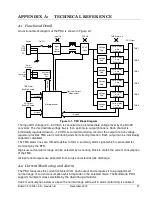
Included here is a full description of Mode A and Mode B operation as it applies to the Multimode
PDU.
(
"
'
'
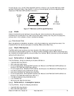
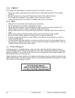
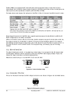
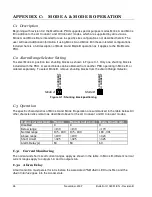
To select M
ODE
A, position two shunting blocks as shown in Figure C-1. Only one shunting block is
included with the PDU. A second block can be obtained from another PDU operating in M
ODE
B, or
ordered separately. To select M
ODE
B, remove shunting blocks from the Alarm Range Selector.
LO
C
U
R
R
E
N
T
H
I
C
U
R
R
E
N
T
LO
C
U
R
R
E
N
T
H
I
C
U
R
R
E
N
T
Mode A
Mode B
Figure C-1: Shunting block positioning
(
7
The specific characteristics of M
ODE
A and M
ODE
B operation are summarized in the table below. All
other characteristics remain as described above for the LO
C
URRENT
and HI
C
URRENT
modes.
/
%
*+
' ( +
' ( 6
' ( 6
! (
#
%
5.2
5.2
5.
%
.2/ ? .4
.2/ ? .4
.4 ? 2 .
(
%
6.B
6.B
62 2
$
'
6A /
6A /
6A /
!
9<
7
7
7
5,,
+ ,+4
The normal and short circuit current ranges apply as shown in the table. In M
ODE
B, different normal
current ranges apply to outputs 1-3 and to outputs 4-6.
,:
-
A fault condition must persist for 60 s before the associated TMA Alarm LED turns R
ED
and the
Alarm Interface goes into the A
LARM
state.
Summary of Contents for Multimode Power Distribution Unit
Page 1: ...Installation and Operation User Guide...
Page 2: ......
Page 4: ...iv November 2007 Bulletin II 102051 EN Revision B 0 1...
Page 31: ......


