Bulletin II-102051-EN • Revision B
November-2007
5
#
1
2 +
. / 0
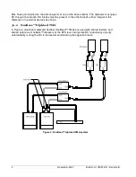
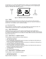
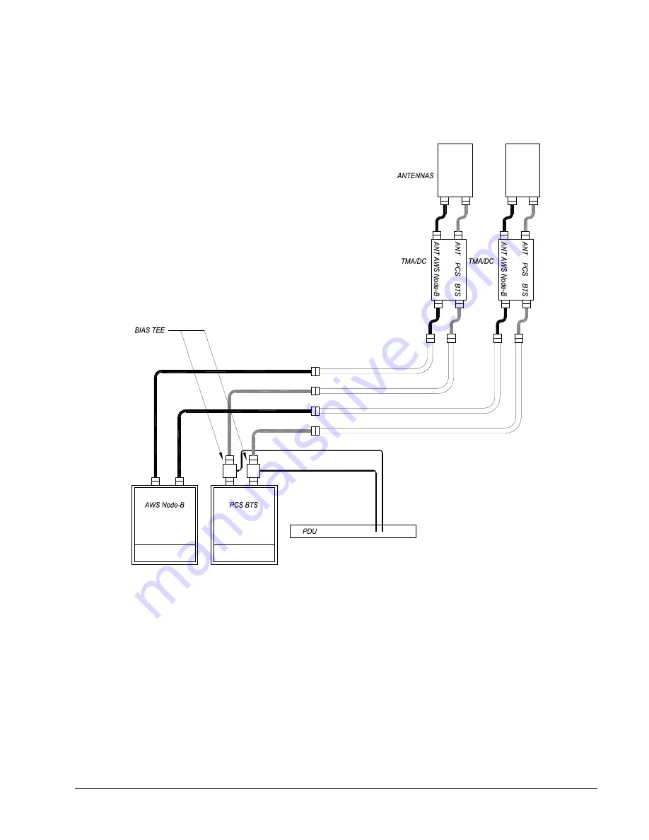
Figure 3 shows a TMA system with Andrew OneBase™ TMAs and separate feeders for each band.
The OneBase™ dual-band TMAs incorporate DC redundancy circuitry that allows DC supply for
both bands to be provided to either BTS/Node-B port.
Figure 3: OneBase™ non-diplexed dual-band TMA system
' ,
"
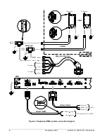
A detailed connection diagram for a typical single-band TMA system is shown in Figure 4. The PDU
receives DC input power from the BTS and outputs a summary alarm signal to the BTS. The Bias
Tee Harness is connected from the PDU to up to six Bias Tees to p12 VDC power to the
TMAs via the feeder cables. Embossed or engraved markings or labels are used to identify the ports
of the Bias Tees and TMAs. All equipment should be properly grounded.
3+ +4 #
0
Twin TMAs include two identical RF paths (main and diversity). Conventional twin TMAs require DC
supply to both BTS ports, similar to two single TMAs. Andrew OneBase™ Twin TMAs incorporate
DC redundancy circuitry. DC supply for both RF paths can be provided to either BTS/Node-B port.
Summary of Contents for Multimode Power Distribution Unit
Page 1: ...Installation and Operation User Guide...
Page 2: ......
Page 4: ...iv November 2007 Bulletin II 102051 EN Revision B 0 1...
Page 31: ......


