3
Installation
3
Installation
3.1
Introduction
The law requires that installation is carried out by a
properly qualified person
Install in accordance with current British Standard Code of
Practice 342 part 2 and British Standards 5440, 5546, 6644,
6700, 6798 and 6891.
3.2
Location
The location chosen for the heater must permit the provision of a
satisfactory flue and an adequate air supply.
The heater must not be installed in a room which contains a
bath or a shower and must not be installed in a bedroom or
bedsitting room.
A clearance of 300mm should be left around the heater for fitting
and servicing purposes and 762mm above the heater for
removal of the flue baffle. The above clearances are
recommended for ease of servicing. They can be reduced if
necessary but a clearance of 300mm must be left in front of
heater for access to the burner and controls. The flue baffle
clearance should also be maintained if possible to avoid
servicing problems.
The floor on which the heater is installed must be flat, level and
of sufficient strength to withstand the weight of the heater when
filled with water, and should satisfy the requirements of the Local
Authority & Building Regulations.
Any combustible material adjacent to the heater must be so
placed or shielded as to ensure that its temperature does not
exceed 65°C.
3.3
Flue System
See
Detailed recommendations for flueing are given in British
Gas booklet IM/11 and BS 5440 part 1. The following
notes are intended to give general guidance:
Note
•
Route. The route of the flue is not critical but, when
planning horizontal runs, potential condensate traps
must be avoided by maintaining a fall of 3° back to the
appliance.
When calculating maximum flue runs, a reduction
must be made of 2M per 90° bend and 1.5M per 45°
bend.
•
Location. The siting of the flue terminal is not critical
with respect to the performance of the unit. However,
areas where the discharge of combustion products
would cause a nuisance should be avoided and it
should be positioned in the wall or roof correctly using
appropriate wall cover plates and flashing kits.
In accessible positions a suitable guard should be
provided.
10
Issue 4 21042018
Summary of Contents for RFF 13/175
Page 8: ...8 Blank Page Issue 4 21042018 ...
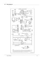
Page 19: ...3 11 Wiring Diagram 19 Issue 4 21042018 ...
Page 50: ...8 Parts List 8 1 General Assembly 50 Issue 4 21042018 ...
Page 51: ...51 Issue 4 21042018 ...
Page 52: ...52 Issue 4 21042018 ...
Page 53: ...53 Issue 4 21042018 ...
Page 54: ...8 2 Control Box Assembly 54 Issue 4 21042018 ...


