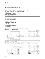
Hydraulic connection
Split System
17
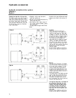
Split System
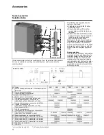
The split system boiler enables the
connection of two returns with different
water temperatures. By evasing the low
loss header the cold return water enters
the condensor of the boiler directly,
without mixing with the high temepra-
ture return water (f.e. from an air heater
circuit). This hydraulic separation in-
creases the efficiency of the system.
The primary boiler pump, controlled by
the boiler managemant unit, ensures a
minimum water flow through the boiler
except for the bottom heat exchanger
(condensor). The system pump of the
low temperature circuit must be dimen-
sioned in such a way, that it can over-
come the boiler resistance.
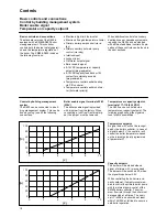
The nominal flow rate in the (warm)
boiler circuit must be minimum 50%
of the total nominal flow rate through
the boiler.
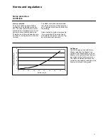
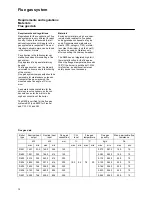
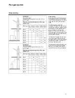
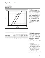
The following data can be used for the dimensioning of the pumps in a split system.
Min. and max. flow rate Q1-Q2
Q
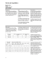
2,min
Q
2,max
(Q
1
+Q
2
)
min
(Q
1
+Q
2
)
max
[m
3
/h] [m
3
/h] [m
3
/h] [m
3
/h]
R601
0
3.0 4.9 8.1
R602 4.0
6.5
10.8
R603 5.1
8.2
13.6
R604 6.1
9.8
16.3
R605 8.1
13.0
21.7
R606 10.2
16.3
27.2
R607 11.5
18.5
30.8
0.10
1.00
10.00
100.00
1.00
10.00
100.00
Q1+Q2 [m3/h]
R1
[
kP
a]
R601-R603
R604-R607
0.00
0.01
0.10
1.00
10.00
100.00
0.10
1.00
10.00
100.00
Q2 [m3/h]
R2
[
kP
a]
R601-R603
R604-R607
R1
R2
Q1
Q2 P2
P1
Q1+Q2
Necessary head pump P2: R
P2
= R2
at Q2
+ R1
at (Q1+Q2)
+ R
System
Necessary head pump P1: R1
at (Q1+Q2)
Summary of Contents for SH60
Page 3: ...3 ...
Page 7: ...Technical description Declaration of conformity 7 ...
Page 26: ...26 UPS32 60F UPS32 120F UPS50 120F UPS65 120F Accessories Plug play kits ...
Page 45: ......
Page 46: ......
Page 47: ......


