Anemoment LLC
21
Data Logger 422 User Manual
AD2 - Analog 2, and Digital 2 Input Connector
The Analog 2 and Digital 2 Connector (J2) is where the user connects the analog and digital channel
2 signals to the DL422.
The JST brand GHR-04V-S in-line snap connector mates with this connector.
NOTE:
Pin 1 is on the
top
as viewed in Figure 8.
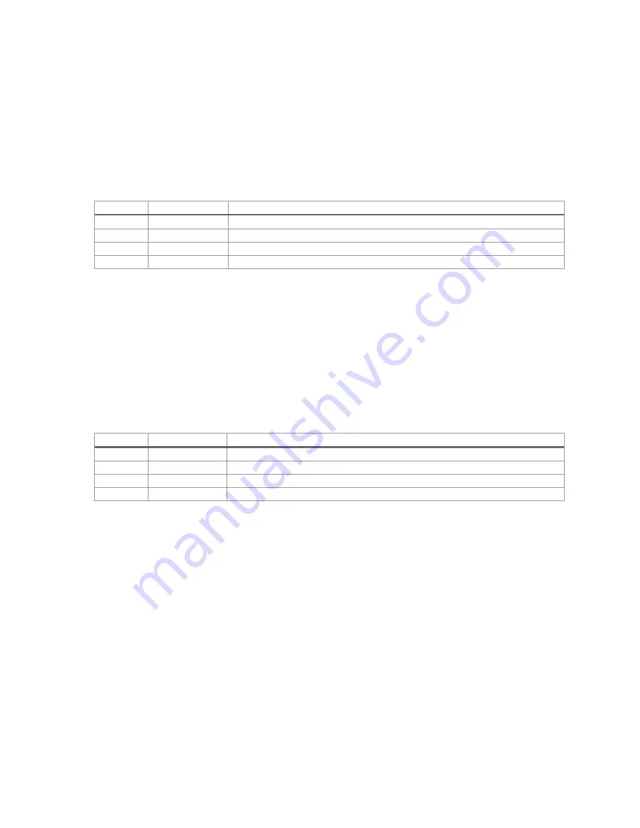
Table 12: Analog 2 and Digital 2 Connector Pin Descriptions
Pin Name Signal Name
Description
1
V_Out
Voltage output of 5V. (Jumper Configurable to 3.3V)
2
GND
Ground
3
ANALOG 1
Analog Input #1. This signal accepts voltage inputs of 0V to 6V.
4
Digital 1
Digital Input #1. This signal accepts voltage of 0V to 3.3V.
QWIIC - External I2C Connector (Reserved for Future Use)
The QWIIC Connector (J10) allows the user to connect external I2C devices that follow the SparkFun
QWIIC connection standard.
Currently, there are no external devices supported.
This feature is reserved for future firmware
expansion.
Currently there is no firmware support for this feature.
NOTE:
Pin 1 is on the
top
as viewed in Figure 8.
Table 13: QWIIC Connector Pin Descriptions
Pin Name Signal Name
Description
1
GND
I2C Signal Ground.
2
3.3V
3.3V for power external I2C peripherals.
3
SDA
I2C SDA Signal
4
SCL
I2C SCL Signal
MicroSD Card Connector
The MicroSD Card connector (J3) accepts a standard MicroSD Card. Data collected by the DL422 is
logged to this card. No data is logged by the DL422 if a MicroSD Card is not present.
The system automatically detects card insertion and removal.
DL422-B MicroSD Card Insertion and Removal
To insert, slide MicroSD Card into the slot with the gold contact pins side facing down, until it clicks
into place. To remove, gently press the edge of the card inward toward the circuit board. When the
card pops out, remove the MicroSD Card from the slot.


