background image

IT

- 8 -

3269830_inst_rev.2 

ITALIANO

MOVIMENTAZIONE E SOLLEVAMENTO

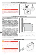
INSTALLAZIONE APPARECCHIATURA

Tutte le fasi di installazione devono essere con-
siderate sin dalla realizzazione del progetto ge-
nerale.
Prima di iniziare tali fasi, oltre alla defi nizione 
della zona di installazione, chi è autorizzato ad 
eseguire queste operazioni dovrà, se necessario, 
attuare un “piano di sicurezza” per salvaguardare 
l’incolumità delle persone direttamente coinvol-
te ed applicare in modo rigoroso tutte le leggi, 
con particolare riferimento a quelle sui cantie-
ri mobili.
La zona di installazione deve essere provvista di 
tutti gli allacciamenti di alimentazione e di scari-
co dei residui di lavorazione. Deve essere adegua-
tamente illuminata ed avere tutti i requisiti igie-
nici e sanitari rispondenti alle leggi vigenti, per 
evitare che gli alimenti vengano contaminati.
Se necessario, individuare l’esatta posizione di 
ogni singola apparecchiatura o sottoinsieme e 
tracciare le coordinate per posizionarli corretta-
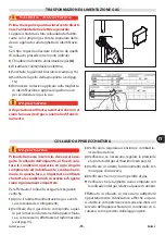
mente (vedi fi gura esemplifi cativa).

Eseguire l’installazione secondo le leggi, le nor-
me e le specifi che vigenti nel paese di utilizzo 
(Decreto ministeriale n°74 del 12/04/96 e UNI-
CIG 87/23). 

VENTILAZIONE LOCALE

Importante

Nel locale dove è installata l’apparecchiatura, 
devono essere presenti delle prese d’aria per 
garantire il corretto funzionamento dell’ap-
parecchiatura e per il ricambio d’aria del loca-
le stesso.

Importante

Le prese d’aria devono avere dimensioni ade-
guate, devono essere protette da griglie e col-
locate in modo da non poter essere ostruite.

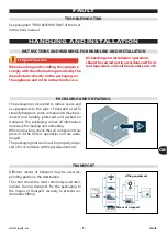
L’apparecchiatura può essere movimentata con 
un dispositivo di sollevamento a forche o a gan-
cio di portata adeguata. Prima di eff ettuare que-
sta operazione, controllare la posizione del bari-
centro del carico. 

Importante

Important

Wichtig

Important

Importante

Nell’inserire il dispositivo di sollevamento, 
fare attenzione ai tubi di alimentazione e sca-
rico.

Summary of Contents for 0N1CP1GH

Page 1: ...äts müssen die Anleitungen aufmerksam durchgelesen werden Lire attentivement les instructions avant d installer et d utiliser l appareil Léanse atentamente las instrucciones antes de instalar y utilizar el aparato Il mancato rispetto delle istruzioni fa decadere la garanzia del fabbricante In the event of failure to comply with the instructions the manufacturer s warranty shall cease to apply Die ...

Page 2: ...lizia chiudere sempre il rubinetto alimentazione gas disattivare l alimentazione elettrica tra mite l interruttore sezionatore e lasciare raf freddare l apparecchiatura Cautela Avvertenza Durante l utilizzo di detergenti è obbligato rio utilizzare guanti in gomma maschera anti inalazione ed occhiali di protezione secondo le norme di sicurezza vigenti Cautela Avvertenza Non usare prodotti che conte...

Page 3: ...RMAZIONE 5 ACCESSORI A RICHIESTA 6 SICUREZZA 6 ISTRUZIONI E AVVERTENZE PER LA SICUREZZA 6 ISTRUZIONI E AVVERTENZE PER LA SICUREZZA SULL IMPATTO AMBIENTALE 7 USO E FUNZIONAMENTO 8 ISTRUZIONI E AVVERTENZE PER L USO E IL FUNZIONAMENTO 8 DESCRIZIONE COMANDI 8 ACCENSIONE E SPEGNIMENTO APPARECCHIATURA 9 RIEMPIMENTO E SVUOTAMENTO VASCA 10 INATTIVITÀ PROLUNGATA DELL APPARECCHIATURA 11 ISTRUZIONI ED AVVERT...

Page 4: ...iginale italiano e vengono tradotte nelle altre lingue per soddi sfare le esigenze legislative e o commerciali La lettura di tali informazioni permetterà di evitare rischi alla salute e alla sicurezza delle persone e danni economici Conservare questo manuale per tutta la durata di vita dell apparecchiatura in un luogo noto e facilmente accessibile per averlo sempre a disposizione nel momento in cu...

Page 5: ...o b14 Tensione V b15 Frequenza Hz b16 Potenza elettrica assorbita W b17 Indicatore tensione collaudo b18 Data di costruzione C Targa gas collaudo c1 Tipo di gas c2 Pressione gas L installatore dovrà scegliere e applicare la tar ghetta A a fianco della targhetta di identifica zione relativa al paese di utilizzo e dovrà contras segnare a quale categoria appartiene Tipo A scarico standard Se il gas d...

Page 6: ...rati dal bruciatore C Spia rete per segnalare l attivazione dell ali mentazione elettrica D Spia sicurezza per segnalare che il livello dell acqua in vasca è sceso al di sotto del livello minimo E Erogatoreacqua perdirezionareilflussodell acqua F Manopola comando acqua per riempire la vasca nelle diverse modalità G Manopola livello potenza per regolare la potenza di riscaldamento su uno dei tre li...

Page 7: ...igore ed utilizzare solo in ambienti bene areati F Pericolo di scottatura fare attenzione alle superfici calde G Marcatura CE indica che l apparecchiatura è conforme a tutte le pertinenti disposizioni SEGNALI DI SICUREZZA E INFORMAZIONE legislative di prodotto applicabili H Pericolo generico è vietato il funzionamen to a secco L Pericolo generico svuotare completamente la vasca dopo l uso A B B C ...

Page 8: ...le persone danni ai beni posti nelle vicinanze e danni economici Tutti gli interventi di manutenzione che richie dono una precisa competenza tecnica o parti colari capacità o qualifiche previste dalla legge devono essere eseguiti esclusivamente da per sonale debitamente qualificato e o abilitato e comunque con esperienza riconosciuta e acqui sita nel settore specifico di intervento Per mantenere l...

Page 9: ...erenziato in funzione della composi zione dei diversi materiali e nel rispetto delle leggi vigenti in materia In fase di dismissione dell apparecchiatura selezionare tutti i componenti in funzione delle loro caratteristiche e provvedere allo smaltimento differenziato Importante Important Wichtig Important Importante Non disperdere materiale inquinante nell ambiente Effettuare lo smaltimento nel ri...

Page 10: ...ti devono applicare tut te le norme di sicurezza e leggere con atten zione la descrizione dei comandi e la messa in servizio DESCRIZIONE COMANDI A Manopola comando acqua per riempire la vasca nelle diverse modalità B Manopola livello potenza per regolare la potenza di riscaldamento su uno dei tre livelli C Spia rete per segnalare l attivazione dell ali mentazione elettrica D Spia sicurezza per seg...

Page 11: ... senso an tiorario pos 2 per accendere il bruciatore 7 Ruotare la manopola B in una delle altre posi zioni pos 5 per regolare la potenza del brucia tore a valori inferiori Spegnimento 1 Ruotare la manopola B in senso antiorario pos 2 per disattivare l alimentazione elettrica dell apparecchiatura 2 Ruotare la manopola A in senso antiorario pos 1 per arrestare l erogazione 3 Premere e ruotare la man...

Page 12: ...e continua che mantiene costantemente il livello dell acqua all interno della vasca Importante Important Wichtig Important Importante Se l acqua scende al di sotto del livello mi nimo si attiva automaticamente la modalità riempimento rapido automatico Riempimento rapido libero Ruotare la manopola A in posizione 3 per ri empire la vasca fino al livello desiderato Importante Important Wichtig Import...

Page 13: ... di garantire un corretto uso dell apparec chiatura è bene applicare i seguenti consigli Utilizzare esclusivamente gli accessori indicati dal Fabbricante Mantenere costantemente pulita l apparecchia tura e le zone limitrofe Per la pulizia utilizzare esclusivamente prodotti detergenti per uso alimentare Prima di riempire la vasca verificare che la leva di scarico B sia in posizione CLOSED Mantenere...

Page 14: ...e si considera che l apparecchiatura è utilizzata per la preparazione di prodotti alimentari per l uo mo è necessario prestare particolare cura a tutto ciò che riguarda l igiene e mantenere costante mente pulita l apparecchiatura e tutto l ambiente circostante Importante Important Wichtig Important Importante Prima di iniziare qualsiasi intervento di pulizia chiudere sempre il rubinetto ali mentaz...

Page 15: ... eseguito correttamente Verificare il collegamento del pressostato Contattare il servizio assistenza Allacciamento idrico non ese guito correttamente Verificare il collegamento idrico Contattare il servizio assistenza Con la manopola comando acqua in posizione 2 Rab bocco lento automatico il rabbocco lento non avviene Collegamento all elettrovalvola mantenimento acqua non eseguito correttamente Ve...

Page 16: ...ing the master switch and allow the appliance to cool Caution Warning When using detergents rubber gloves pro tective mask and safety goggles must be worn in accordance with the relevant safety regula tions Caution Warning Never use products containing substances harmful or hazardous for health solvents pe troleum spirits etc Caution Warning Before doing any work cut off the mains elec tricity sup...

Page 17: ...NFORMATION SIGNS 5 OPTIONAL ACCESSORIES 6 SAFETY 6 INSTRUCTIONS AND WARNINGS FOR SAFETY 6 SAFETY WARNINGS AND INSTRUCTIONS CONCERNING ENVIRONMENTAL IMPACT 7 USE AND OPERATION 8 INSTRUCTIONS AND WARNINGS FOR USE AND OPERATION 8 DESCRIPTION OF CONTROLS 8 SWITCHING THE APPLIANCE ON AND OFF 9 FILLING AND EMPTYING THE WELL 10 LENGTHY DOWNTIMES OF APPLIANCE 11 INSTRUCTIONS AND WARNINGS FOR USE 11 SERVIC...

Page 18: ...ed by the manufac turer in the original language Italian and is translated into other languages to meet legal and or business requirements Reading this information will avoid health and safety risks to people and financial losses Keep this manual in a clearly identified safe place throughout the working life of the appli ance so that it will always be available when required for consultation The m...

Page 19: ...V b15 Frequency Hz b16 Electricity power consumption W b17 Test voltage indicator b18 Date of construction C Testing gas plate c1 Type of gas c2 Gas pressure The installer must select the plate A and apply it alongside the nameplate relating to the country of use and must mark the relative appliance class Type A standard fume exhaust vent If the appliance is to be used with the same type of gas as...

Page 20: ...enerated by the burner C Mains light indicates that the appliance is receiving electrical power D Safety indicator light to report that the water level in the tank has dropped below the minimum level E Adjustablewaterspout directstheflowofwater F Water control knob for filling the well in the various ways available G Power level knob to adjust the heating inten sity to one of the three levels H Bu...

Page 21: ... relevant regulations must be complied with Install in complian ce with the relevant regulations and use in well ventilated premises only F Burn hazard watch out for hot surfaces G CE marking this indicates that the equip ment is compliant with all relevant laws ap plicable to the product SAFETY AND INFORMATION SIGNS H General hazard dry operation is forbidden L General hazard drain the well compl...

Page 22: ...people damage to nearby goods and financial losses All maintenance work that requires precise technical expertise or particular skills or qualifi cations for legal reasons should be carried out by suitably trained and or qualified staff and in any case with recognised experienced gained in the specific field of intervention To maintain hygiene and protect the food processed from all forms of conta...

Page 23: ...elevant laws in the country of use During use and maintenance do not dump pollutants oils fats etc in the environment implement separate disposal as appropriate to the composition of the various materials and in compliance with the relevant laws If the appliance is scrapped sort all compo nents by characteristics and dispose of them separately Important Do not dump pollutant material in the envi r...

Page 24: ...ments users must also implement all safety regulations and read the description of the controls and the start up procedure carefully DESCRIPTION OF CONTROLS A Water control knob for filling the well in the various ways available B Power level knob to adjust the heating inten sity to one of the three levels C Mains light indicates that the appliance is receiving electrical power D Safety indicator ...

Page 25: ...b E and turn it anti clockwise pos 2 to light the burner 7 Turn the knob B to one of the other positions pos 5 to adjust the burner intensity to lower values Turning off 1 Turn the knob B anti clockwise pos 2 to turn off the electricity supply 2 Turn the knob A anti clockwise pos 1 to stop delivery 3 Press the knob E and turn it clockwise pos 3 to turn off the burner The pilot light will remain on...

Page 26: ...rn the knob A to 2 for a slow continuous flow of water that keeps the water level inside the well constant Important If the water drops below the minimum level the quick automatic top up mode is auto matically triggered Quick no limits filling Turn the knob A to 3 to fill the tank to the level required Important When filling is completed it will be necessa ry to turn the knob A to another position...

Page 27: ... USE OPEN CLOSED B A To ensure correct use of the appliance the following rules should be adopted Use only the accessories recommended by the manufacturer Always keep the appliance and the surroun ding areas clean When cleaning use only food approved detergents Before filling the tank make sure the drain lever B is on CLOSED Keep the water boiling constantly and ensure correct starch overflow drai...

Page 28: ...ng order CLEANING INSTRUCTIONS Since the appliance is used for preparing foods for human consumption special care must be paid to everything relating to hygiene and the appliance and the entire surrounding environment must constantly be kept clean Important Before starting any cleaning operation always turn off the gas supply tap cut off the electri city supply using the master switch and allow th...

Page 29: ... out of the tap Pressure switch connection not made correctly Check the pressure switch con nection Contact the after sales service Water connection not made correctly Check the water connection Contact the after sales service When the water control knob is turned to 2 Slow automa tic top up slow filling does not take place Water level maintenance sole noid valve connection not made correctly Chec...

Page 30: ...abkühlen lassen Vorsicht Achtung Die geltenden Sicherheitsbestimmungen schreiben vor dass bei derVerwendung von Reinigungsmitteln Gummihandschuhe Atemschutzmaske und Schutzbrille zu tragen sind Vorsicht Achtung Verwenden Sie keine Produkte die Stoffe en thalten welche für die menschliche Gesun dheit schädlich und gefährlich sind Lösemit tel Benzin usw Vorsicht Achtung Vor Ausführung irgendeines Ei...

Page 31: ... 5 OPTIONALES ZUBEHÖR 6 SICHERHEIT 6 ANWEISUNGEN UND WARNHINWEISE FÜR DIE SICHERHEIT 6 SICHERHEITSVORSCHRIFTEN IN HINBLICK AUF DIE UMWELTBELASTUNG 7 GEBRAUCH UND BETRIEB 8 ANWEISUNGEN UND WARNHINWEISE FÜR DIE BEDIENUNG UND BETRIEB 8 BESCHREIBUNG DER BEDIENELEMENTE 8 EIN UND AUSSCHALTEN DES GERÄTS 9 FÜLLEN UND ENTLEEREN DES BECKENS 10 LÄNGERER STILLSTAND DES GERÄTS 11 ANWEISUNGEN UND WARNHINWEISE F...

Page 32: ...e Italienisch bereitgestellt und in andere Sprachen übersetzt um den ge setzlichen bzw handelstechnischen Bedürfnis sen gerecht zu werden Die Lektüre dieser Informationen ermöglicht die Vermeidung von Gesundheits und Sicherheits risiken für Personen und wirtschaftlichen Schä den Bewahren Sie dieses Handbuch für die gesamte Lebensdauer des Gerätes an einem bekannten und leicht zugänglichen Ort auf ...

Page 33: ...jahr C Testgasschild c1 Gastyp c2 Gasdruck Der Installateur muss das geeignete Schild A auswählen neben dem Schild für das Benutzer land aufbringen und mit dem Kennzeichen für die betreffende Kategorie versehen Typ A Standardabzug Wenn das verwendete Gas mit dem überein stimmt welches der Hersteller beim Testlauf verwendet hat so ist es für die Abnahme ausreichend das Schild C zu entfernen und die...

Page 34: ...ase C Kontrollleuchte Stromzufuhr zur Anzeige der Stromzufuhr D Sicherheits Kontrollleuchte Zeigt an dass das Wasserniveau im Behälter unter das Min destniveau gesunken ist E Wasserdüse umdenWasserstrahlauszurichten F SchalterWasser zum Füllen des Wasserbe ckens mit den verschiedenen Modalitäten G Drehknopf Leistungsniveau Um die Heizlei stung auf eine der drei Stufen einzustellen H Bedienknebel B...

Page 35: ...chtung der Vorschriften für die Installation und Inbetriebnahme wird keine Haftung übernommen F Verbrennungsgefahr Vorsicht vor heißen Flächen SICHERHEITSHINWEISE UND INFORMATIONEN G CE Kennzeichen Es weist darauf hin dass das Gerät alle für das Produkt anwendbaren einschlägigen gesetzlichen Vorschriften erfüllt H Allgemeine Gefahr Der Trockenbetrieb ist verboten L Allgemeine Gefahr Das Becken nac...

Page 36: ...ätes kann sowohl die Sicherheit als auch die Gesundheit der Personen gefährden Gegenstände die sich in seiner Nähe befinden beschädigen und wirt schaftliche Schäden verursachen Alle Wartungseingriffe die technisches Fach wissen oder spezielle Fähigkeiten oder eine ge setzlich vorgeschriebene Ausbildung erfordern dürfen ausschließlich von entsprechend ausge bildetem bzw zugelassenem Personal mit na...

Page 37: ...en einschlägigen Bestimmungen getrennt entsorgt werden Wenn das Gerät endgültig außer Betrieb ge nommen wird müssen alle seine Komponen ten in Abhängigkeit von ihren Eigenschaften getrennt entsorgt werden Wichtig Umweltschädliche Stoffe dürfen nicht in die Umwelt gelangen Die Entsorgung in Einklang mit den geltenden gesetzlichen Bestimmun gen vornehmen Beim täglichen Gebrauch des Geräts ist die st...

Page 38: ...ußerdem alle Sicherheitsvorschriften beach ten Sie müssen ferner die Beschreibung der Bedieneinrichtungen und der Inbetriebnahme aufmerksam lesen BESCHREIBUNG DER BEDIENELEMENTE A Schalter Wasser zum Füllen des Wasserbe ckens mit den verschiedenen Modalitäten B Drehknopf Leistungsniveau Um die Heizleis tung auf eine der drei Stufen einzustellen C KontrollleuchteStromzufuhr zur Anzeige der Stromzuf...

Page 39: ... den Brenner einzuschalten 7 Den Drehknopf B in eine der anderen Po sitionen drehen Pos 5 um die Leistung des Brenners auf geringere Werte einzustellen Abschaltung 1 Den Schalters B gegen den Uhrzeigersinn Pos 2 drehen um die Stromzufuhr zu un terbrechen 2 Den Drehknopf A entgegen dem Uhrzei gersinn Pos 1 entgegen dem Uhrzeigersinn drehen um die Versorgung zu stoppen 3 Drücken und drehen Sie den S...

Page 40: ... und konti nuierlichen Wasserzulauf der den Wasserpegel im Becken konstant hält in Schaltstellung 2 drehen Wenn der Wasserpegel unter das Mini mum sinkt wird automatisch die Modalität Schnelles automatisches Nachfüllen akti viert Schnelles freies Füllen Den Schalter A und in Schaltstellung 3 drehen um das Becken bis zum gewünschten Füllstand zu füllen Wichtig Nach dem Füllen muss der Drehknopf A i...

Page 41: ...eine korrekte Anwendung des Gerätes zu gewährleisten sollten folgende Ratschläge befolgt werden Verwenden Sie ausschließlich das vom Herstel ler angegebene Zubehör Das Gerät und den umliegenden Bereich stets sauber halten Zum Reinigen nur lebensmitteltaugliche Reini ger verwenden Vor dem Füllen der Wanne sicherstel len dass der Hebel für den Auslass B in Position CLOSED ist Dafür sorgen dass das W...

Page 42: ...tionstüchtigkeit der Stromanlage prüfen REINIGUNG DES GERÄTS Da das Gerät zur Zubereitung von Speisen für den Menschen eingesetzt wird ist besondere Sorgfalt auf die Hygiene geboten Das Gerät und dessen näheres Umfeld müssen konstant sauber gehalten werden Wichtig Vor Beginn jeglicher Reinigungsarbeiten stets den Gashahn schließen die Spannungsver sorgung mit demTrennschalter unterbrechen und das ...

Page 43: ...asser aus dem Hahn Anschluss an den Druckschalter nicht richtig ausgeführt Anschluss an den Druckschalter überprüfen Kontaktieren Sie den Kunden dienst Wasseranschluss nicht richtig ausgeführt Wasseranschluss überprüfen Kontaktieren Sie den Kunden dienst Wenn sich der Wasser Schalter in der Schaltstellung 2 befindet Langsames automatisches Nachfüllen funktioniert das langsame Füllen nicht Anschlus...

Page 44: ...ntation électrique par l in terrupteur sectionneur et laisser refroidir l ap pareil Attention Lorsqu on utilise des détergents il est obli gatoire de porter des gants en caoutchouc un masque de protection respiratoire et des lunettes de protection conformément aux normes de sécurité en vigueur Attention Ne pas utiliser de produits qui contiennent des substances dangereuses pour la santé des per so...

Page 45: ... 6 SÉCURITÉ 6 INSTRUCTIONS ET MISES EN GARDE POUR LA SÉCURITÉ 6 INSTRUCTIONS ET MISES EN GARDE DE SÉCURITÉ POUR L IMPACT ENVIRONNEMENTAL 7 UTILISATION ET FONCTIONNEMENT 8 INSTRUCTIONS ET AVERTISSEMENTS POUR L UTILISATION ET FONCTIONNEMENT 8 DESCRIPTION DES COMMANDES 8 ALLUMAGE ET EXTINCTION DE L APPAREIL 9 REMPLISSAGE ET VIDANGE DE LA CUVE 10 INUTILISATION PROLONGÉE DE L APPAREIL 11 INSTRUCTIONS E...

Page 46: ...gue originale italien et sont tra duites dans les autres langues afin de satisfaire les exigences législatives et ou commerciales La lecture de ces informations permettra d éviter les risques pour la santé et la sécurité des per sonnes et dommages économiques Conserver ce manuel pour toute la durée de vie de l appareil dans un lieu connu et facilement accessible pour l avoir toujours à disposition...

Page 47: ... essai b14 Tension V b15 Fréquence Hz b16 Puissance électrique absorbée W b17 Indicateur de tension d essai b18 Date de fabrication C Plaque du gaz d essai c1 Type de gaz c2 Pression du gaz L installateur devra choisir et appliquer la plaque A à côté de la plaque d identification relative au pays d utilisation et devra reporter la catégorie d appartenance Type A évacuation standard Si le gaz d uti...

Page 48: ... le brûleur C Voyant de réseau pour signaler l activation de l alimentation électrique D Voyant sécurité pour signaler que le niveau de l eau dans le bac est descendu en dessous du niveau minimum E Distributeurd eau pourdirigerlefluxdel eau F Manette de commande de l eau pour remplir la cuve dans les différents modes G Poignéeniveaupuissance pourréglerlapuis sance de chauffage sur un des trois niv...

Page 49: ...ux normes en vigueur et n utiliser que dans des pièces bien aérées F Risque de brûlure attention aux surfaces chaudes G Marquage CE indique que l équipement est conforme à toutes les dispositions législatives pertinentes pour les produits applicables SIGNAUX DE SÉCURITÉ ET INFORMATION H Risque générique le fonctionnement à sec est interdit L Risque générique Vider complètement la cuve après emploi...

Page 50: ...s des dommages aux biens placés à proximité et des dommages économiques Toutes les interventions de maintenance qui né cessitent une compétence technique précise ou de particulières capacités ou qualifications pré vues par la loi doivent être effectuées exclusive ment par un personnel dûment qualifié et ou habilité et possédant en tout cas une expérience reconnue et acquise dans le secteur spécifi...

Page 51: ...c et effectuer la collecte différenciée des déchets en fonction de la composition des différentes pièces et en respectant les lois en vigueur en la matière Si l on veut supprimer l appareil sélectionner tous les composants en fonction de leurs ca ractéristiques et effectuer la collecte différen ciée Important Ne pas évacuer les matières polluantes dans l atmosphère Effectuer l élimination dans le ...

Page 52: ...itions doivent appliquer toutes les normesdesécuritéetlireattentivementlades cription des commandes et la mise en marche DESCRIPTION DES COMMANDES A Manette de commande de l eau pour remplir la cuve dans les différents modes B Poignéeniveaupuissance pourréglerlapuis sance de chauffage sur un des trois niveaux C Voyant de réseau pour signaler l activation de l alimentation électrique D Voyant sécur...

Page 53: ... et tourner la manette E en sens anti horaire pos 2 pour allumer le brûleur 7 Tourner la poignée B dans une des autres positions pos 5 pour régler la puissance du brûleur à des valeurs inférieures Extinction 1 Tourner la manette B en sens anti horaire pos 2 pour désactiver l alimentation électri que 2 Tourner la poignée A dans le sens antihoraire pos 1 pour arrêter la distribution 3 Presser et tou...

Page 54: ...2 pour ef fectuer une arrivée lente et continue qui main tient constant le niveau de l eau à l intérieur de la cuve Important Si l eau descend au dessous du niveau mini mum le mode remplissage rapide automa tique s active automatiquement Remplissage rapide libre Tourner la manette A en position 3 pour rem plir la cuve jusqu au niveau désiré Important Après avoir effectué le remplissage il est né c...

Page 55: ... de garantir une utilisation correcte de l appareil suivre ces conseils Utiliser exclusivement les accessoires indiqués par le fabricant L appareil et les zones environnantes doivent être constamment propres Pour le nettoyage utiliser exclusivement des produits détergents pour usage alimentaire Avantderemplirlebac s assurerquelelevierde déchargement B soit en position CLOSED Maintenir constante l ...

Page 56: ...OYAGE DE L APPAREIL Étant donné que l appareil est utilisé pour la pré paration de produits alimentaires pour l homme il faut faire attention à tout ce qui concerne l hy giène l appareil et tout ce qui l entoure doivent toujours être très propres Important Avant de commencer toute opération de net toyage fermer le robinet d alimentation du gaz couper l alimentation électrique par l in terrupteur s...

Page 57: ...qui n est pas exécuté correctement Vérifier le raccordement du pressostat Contacter le service assistance Raccordement hydrique qui n est pas exécuté correctement Vérifier le raccordement hydrique Contacter le service assistance Avec la manette de com mande de l eau en position 2 Remplissage lent automati que le remplissage lent n a pas lieu Raccordement à l électrovalve de maintien de l eau qui n...

Page 58: ...ntación del gas desconectar la alimentación eléctrica por medio del interruptor aislador y dejar que el aparato se enfríe Precaución advertencia Al aplicar los detergentes es obligatorio utili zar guantes en goma mascarilla contra inhala ciones y gafas de protección en conformidad con lo dispuesto por las normas vigentes sobre seguridad Precaución advertencia No usar productos que contengan sustan...

Page 59: ...IÓN 5 ACCESORIOS BAJO PEDIDO 6 SEGURIDAD 6 INSTRUCCIONES Y ADVERTENCIAS PARA LA SEGURIDAD 6 INSTRUCCIONES Y ADVERTENCIAS DE SEGURIDAD PARA EL IMPACTO AMBIENTAL 7 USO Y FUNCIONAMIENTO 8 INSTRUCCIONES Y ADVERTENCIAS PARA EL USO Y FUNCIONAMIENTO 8 DESCRIPCIÓN DE LOS MANDOS 8 ENCENDIDO Y APAGADO DEL APARATO 9 LLENADO Y VACIADO DE LA CUBA 10 PERÍODO PROLONGADO DE INACTIVIDAD DEL EQUIPO 11 INSTRUCCIONES...

Page 60: ...isfacer necesidades comerciales y o requisitos estable cidos en la Ley La lectura de esta información permitirá evitar riesgos a la salud y la seguridad de las personas y daños económicos Conservar este manual durante toda la vida útil del equipo en un lugar conocido y fácilmente ac cesible a fin de tenerlo a disposición cuando sea necesario consultarlo El fabricante se reserva el derecho de aport...

Page 61: ... Hz b16 Potencia eléctrica absorbida W b17 Indicador tensión de prueba b18 Fecha de fabricación C Placa gas prueba de funcionamiento c1 Tipo de gas c2 Presión del gas El instalador deberá seleccionar y fijar la placa A al lado de la placa de identificación relativa al país de uso y deberá marcar la categoría a la cual pertenece Tipo A descarga estándar Si el gas de uso es el mismo usado por el fab...

Page 62: ...cuar los humos generados por el quemador C Testigo red para señalar la activación de la alimentación eléctrica D Testigo de seguridad para señalar que el nivel del agua en la cuba ha descendido por debajo del nivel mínimo E Grifodeagua paraorientarelflujodelagua F Mando del agua para llenar la cuba en las diferentes modalidades G Selector del nivel de potencia para regular la potencia de calentami...

Page 63: ...or mativa vigente y utilizar sólo en ambientes adecuadamente aireados F Peligro de quemaduras prestar atención a las superficies calientes SEÑALIZACIONES DE SEGURIDAD E INFORMACIÓN G Marcado CE indica que el aparato es confor me con todas las disposiciones legislativas pertinentes de producto aplicables H Peligro genérico está prohibido el funcio namiento en seco L Peligro genérico Después del uso...

Page 64: ... o de una capacidad especial deben ser efectuadas ex clusivamente por personal calificado y con expe riencia reconocida y adquirida en el sector específi co de la intervención Para mantener la higiene y proteger los alimen tos trabajados respecto de cualquier fenómeno de contaminación es necesario limpiar proli jamente los elementos que entran en contacto directa o indirectamente con los alimentos...

Page 65: ...nantes aceites grasas etc Su eliminación deberá efectuarse de modo selectivo en función de la composición de los diferentes materiales y en conformidad con lo dispuesto por las leyes vigentes en esta materia Al efectuar el desguace del aparato seleccio nar todos los componentes en función de sus características y clasificarlos de modo selecti vo según su grado de posible eliminación o reciclaje Im...

Page 66: ...ligarse a cumplir estos requisitos deben aplicar todas las nor mas de seguridad y leer con atención la des cripción de los mandos y de la puesta en ser vicio DESCRIPCIÓN DE LOS MANDOS A Mandodelagua para llenar la cuba en las dife rentes modalidades B Selector del nivel de potencia para regular la potencia de calentamiento en uno de los tres niveles C Testigo red para señalar la activación de la a...

Page 67: ...ando E en sentido an tihorario pos 2 para encender el quemador 7 Gire el selector B hacia una de las otras posiciones pos 5 para regular la potencia del quemador a valores inferiores Apagado 1 Gire el mando B en sentido antihorario pos 2 para interrumpir la alimentación eléc trica 2 Gire el selector A hacia la izquierda pos 1 para detener la dispensación 3 Presionar y girar el mando E en sentido h...

Page 68: ...istro lento y continuo que mantiene constante el nivel del agua en el interior de la cuba Importante Important Wichtig Important Importante Al descender el agua por debajo del nivel mínimo se activa automáticamente la modali dad de rellenado rápido automático Llenado rápido libre Situar el mando A en posición 3 para llenar la cuba hasta alcanzar el nivel requerido Importante Important Wichtig Impo...

Page 69: ...ERTENCIAS PARA EL USO OPEN CLOSED B A A fin de garantizar un uso correcto del equipo aplicar las siguientes recomendaciones Utilizar exclusivamente los accesorios indicados por el fabricante Mantener constantemente limpio el aparato y las zonas a él próximas La limpieza deberá efectuarse utilizando úni camente productos detergentes previstos para uso alimentario Antes de llenar la cuba compruebe q...

Page 70: ...ia de que el equipo es utilizado para la preparación de productos ali menticios para el consumo humano es necesario prestar especial atención a todo lo referente a la higiene manteniendo siempre limpio tanto el equipo como el ambiente que lo rodea Importante Important Wichtig Important Importante Antes de realizar cualquier operación de lim pieza cerrar siempre la llave de alimentación del gas des...

Page 71: ...to Controlar la eficiencia de la cone xión con el presostato Contactar el servicio de asistencia Conexión hídrica efectuada de modo incorrecto Controlar le eficiencia de la conexión hídrica Contactar el servicio de asistencia Con el mando del agua dispuesto en 2 Rellenado lento automático no se verifica el llenado lento Conexión con la electroválvula de mantenimiento agua efec tuada de modo incorr...

Page 72: ......

Page 73: ...nt d installer et d utiliser l appareil Léanse atentamente las instrucciones antes de instalar y utilizar el aparato Il mancato rispetto delle istruzioni fa decadere la garanzia del fabbricante In the event of failure to comply with the instructions the manufacturer s warranty shall cease to apply Die Missachtung der Anleitungen hat den Verfall der vom Hersteller gewährten Garantie zur Folge Le no...

Page 74: ......

Page 75: ...REZZA 5 ISTRUZIONI E AVVERTENZE PER LA SICUREZZA SULL IMPATTO AMBIENTALE 5 MANUTENZIONE 6 ISTRUZIONI ED AVVERTENZE PER LA MANUTENZIONE 6 CONTROLLO PRESSIONE GAS 6 GUASTI 7 RICERCA GUASTI 7 MOVIMENTAZIONE E INSTALLAZIONE 7 ISTRUZIONI E AVVERTENZE PER LA MOVIMENTAZIONE E INSTALLAZIONE 7 IMBALLO E DISIMBALLO 7 TRASPORTO 7 MOVIMENTAZIONE E SOLLEVAMENTO 8 INSTALLAZIONE APPARECCHIATURA 8 VENTILAZIONE LO...

Page 76: ...E REGOLAZIONI 14 REGOLAZIONE ARIA PRIMARIA BRUCIATORE 14 SOSTITUZIONI PARTI 15 ISTRUZIONI ED AVVERTENTE PER LA SOSTITUZIONE PARTI 15 SOSTITUZIONE UGELLO BRUCIATORE 15 SOSTITUZIONE UGELLO SPIA PILOTA 16 DISMISSIONE DEMOLIZIONE E SMALTIMENTO APPARECCHIATURA 16 ALLEGATI ANNEXES I IX ...

Page 77: ...zioni sono fornite dal Fabbrican te nella propria lingua originale italiano e ven gono tradotte nelle altre lingue per soddisfare le esigenze legislative e o commerciali La lettura di tali informazioni permetterà di evi tare rischi alla salute e alla sicurezza delle perso ne e danni economici Conservare questo manuale per tutta la durata di vita dell apparecchiatura in un luogo noto e fa cilmente ...

Page 78: ...do b14 Tensione V b15 Frequenza Hz b16 Potenza elettrica assorbita W b17 Indicatore tensione collaudo b18 Data di costruzione C Targa gas collaudo c1 Tipo di gas c2 Pressione gas L installatore dovrà scegliere e applicare la tar ghetta A a fianco della targhetta di identifica zione relativa al paese di utilizzo e dovrà contras segnare a quale categoria appartiene Tipo A scarico standard Se il gas ...

Page 79: ...Vedi paragrafo SEGNALI DI SICUREZZA E INFOR MAZIONE del manuale Istruzioni per l utilizza tore ACCESSORI A RICHIESTA Vedi paragrafo ACCESSORI A RICHIESTA del manuale Istruzioni per l utilizzatore SICUREZZA ISTRUZIONI E AVVERTENZE PER LA SICUREZZA Vedi paragrafo ISTRUZIONI E AVVERTENZE PER LA SICUREZZA del manuale Istruzioni per l uti lizzatore ISTRUZIONI E AVVERTENZE PER LA SICUREZZA SULL IMPATTO ...

Page 80: ...l intervento di manutenzione l ope ratore sia sempre in grado di poter control lare che la spina sia disinserita dalla presa di corrente Ogni 100 ore di esercizio fare eseguire da opera tori esperti e autorizzati le seguenti operazioni Controllo pressione gas e tenuta impianto Verifica efficienza termocoppia di sicurezza Verificare efficienza impianto elettrico CONTROLLO PRESSIONE GAS Per questa o...

Page 81: ...Per facilitare il trasporto la spedizio ne può essere eseguita con alcuni componenti smontati ed opportunamente protetti e imballa ti Sull imballo sono riportate tutte le informazio ni necessarie ad effettuare il carico e lo scarico In fase di disimballo controllare l integrità e l e satta quantità dei componenti Il materiale di imballo va opportunamente smal tito nel rispetto delle leggi vigenti ...

Page 82: ...cessario individuare l esatta posizione di ogni singola apparecchiatura o sottoinsieme e tracciare le coordinate per posizionarli corretta mente vedi figura esemplificativa Eseguire l installazione secondo le leggi le nor me e le specifiche vigenti nel paese di utilizzo Decreto ministeriale n 74 del 12 04 96 e UNI CIG 87 23 VENTILAZIONE LOCALE Importante Nel locale dove è installata l apparecchiat...

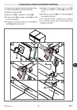
Page 83: ...enso antiorario 4 Collegare le apparecchiature con le viti F e la staffa G parte posteriore 5 Collegare le apparecchiature con la vite H forniita a corredo e la staffa E parte ante riore 6 Rimontare i cruscotti B e le manopole A ad operazione ultimata Per le apparecchiature in batteria sono disponi bili a richiesta diversi kit di allestimento vedi catalogo generale MONTAGGIO APPARECCHIATURE IN BAT...

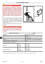
Page 84: ...un rubinetto di intercettazione A per interrompere quando necessario l alimenta zione dell acqua A valle di esso installare dei filtri facilmente rag giungibili Cautela Avvertenza L apparecchiatura deve essere alimentata con acqua potabile con le caratteristiche indicate in tabella ALLACCIAMENTO ACQUA A Valori differenti da questi parametri possono causare corrosioni se combinati con un uso e ambi...

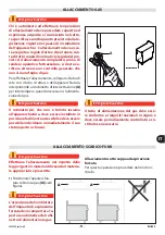
Page 85: ...ettazione A per interrompere quando necessario l alimenta zione del gas Importante Important Wichtig Important Importante Il rubinetto A che non è fornito insieme all apparecchiatura deve essere installato in posizione facilmente accessibile e deve essere possibile individuare immediatamente il suo stato aperto o chiuso A Importante Il tubo di alimentazione del gas deve esse re conforme ai requisi...

Page 86: ...e nel modo indicato 1 Installare se non è presente un interruttore sezionatore automatico A vicino all apparec chiatura con le seguenti caratteristiche Sganciatore termico per regolazione vedi tabella sezione Allegati Interruttore magnetico curva B o C IEC 60898 Sganciatore differenziale regolato a 30 mA 2 Aprire il portello B 3 Svitare la vite per smontare la leva di scarico C 4 Svitare le viti p...

Page 87: ... essere ese guito il collaudo dell impianto al fine di valu tare le condizioni operative di ogni singolo componente ed individuare le eventuali ano malie In questa fase è importante verificare che tutte le condizioni di sicurezza e di igiene siano rigorosamente rispettate Per effettuare il collaudo eseguire le seguenti verifiche 1 Aprire il rubinetto alimentazione gas e verifi care la tenuta dei c...

Page 88: ... gas da allacciare è diverso da quello di col laudo dopo avere eseguito la trasformazione dell alimentazione vedi pag 13 Cautela Avvertenza Le regolazioni devono essere effettuate da personale autorizzato e qualificato nel rispet to delle leggi vigenti in materia REGOLAZIONI A C B D E F REGOLAZIONE ARIA PRIMARIA BRUCIATORE Per questa operazione procedere nel modo in dicato 1 Aprire il portello A 2...

Page 89: ...to di manutenzione l operatore sia sempre in grado di poter controllare che la spina sia di sinserita dalla presa di corrente Qualora sia necessario sostituire dei compo nenti usurati utilizzare esclusivamente dei ri cambi originali Si declina ogni responsabilità per danni a persone o componenti derivanti dall impiego di ricambi non originali e inter venti straordinari che possono modificare i req...

Page 90: ...tituiscano un intralcio e non siano facilmente accessibili Per evitare che l apparecchiatura possa costituire pericoli per le persone e l ambiente è necessa rio scollegare e rendere inutilizzabili tutte le fonti di alimentazione elettrica ecc e scaricare tutti i liquidi eventualmente presenti lubrificanti oli ecc Depositare l apparecchiatura in una zona adatta non facilmente accessibile ed opportu...

Page 91: ...NINGS FOR SAFETY 5 INSTRUCTIONS AND WARNINGS FOR THE SAFETY OF THE ENVIRONMENTAL IMPACT 5 SERVICING 6 INSTRUCTIONS AND WARNINGS FOR SERVICING 6 CHECKING GAS PRESSURE 6 FAULT 7 TROUBLESHOOTING 7 HANDLING AND INSTALLATION 7 INSTRUCTIONS AND WARNINGS FOR HANDLING AND INSTALLATION 7 PACKAGING AND UNPACKING 7 TRANSPORT 7 HANDLING AND LIFTING 8 INSTALLATION OF THE APPLIANCE 8 ROOM VENTILATION 8 ASSEMBLY...

Page 92: ...OR ADJUSTMENTS 14 ADJUSTING BURNER PRIMARY AIR 14 REPLACING PARTS 15 INSTRUCTIONS AND WARNINGS FOR THE REPLACEMENT OF PARTS 15 REPLACEMENT OF THE BURNER NOZZLE 15 REPLACEMENT OF THE PILOT LIGHT INJECTOR 16 EQUIPMENT DECOMMISSIONING DEMOLITION AND DISPOSAL 16 ALLEGATI ANNEXES I IX ...

Page 93: ...ons to the letter This information is provided by the manufactur er in the original language Italian and is trans lated into other languages to meet legal and or business requirements Reading this information will avoid health and safety risks to people and financial losses Keep this manual in a clearly identified safe place throughout the working life of the appliance so that it will always be av...

Page 94: ... V b15 Frequency Hz b16 Electricity power consumption W b17 Test voltage indicator b18 Date of construction C Testing gas plate c1 Type of gas c2 Gas pressure The installer must select the plate A and apply it alongside the nameplate relating to the coun try of use and must mark the relative appliance class Type A standard fume exhaust vent If the appliance is to be used with the same type of gas ...

Page 95: ...GNS See paragraph SAFETY AND INFORMATION SIGNS of the User instructions manual OPTIONAL ACCESSORIES See paragraph OPTIONAL ACCESSORIES of the User instructions manual SAFETY INSTRUCTIONS AND WARNINGS FOR SAFETY See paragraph INSTRUCTIONS AND WARNINGS FOR SAFETY of the User instructions manual INSTRUCTIONS AND WARNINGS FOR THE SAFETY OF THE ENVIRONMENTAL IMPACT See paragraph INSTRUCTIONS AND WARNIN...

Page 96: ...onnected from the power outlet Every 100 working hours have skilled authorised personnel carry out the following operations A check on the gas pressure and system tightness A check on the efficiency of the safety ther mocouple check that the electrical system is in good working order CHECKING GAS PRESSURE To carry out this operation proceed as follows 1 Turn off the gas supply tap 2 Open the hatch...

Page 97: ...ion The chart shows the most commonly used alter natives During transport fix the packaging to the means of transport securely to prevent un desirable shifting FAULT TROUBLESHOOTING See paragraph TROUBLESHOOTING of the User instructions manual Lifting equipment Means of transport PACKAGING AND UNPACKING The packaging is designed to reduce space and as appropriate to the type of transport used To s...

Page 98: ... requirements especial ly those relating to mobile work sites The place of installation must have all the con nections needed to supply the appliance and di spose of the production residues must be suita bly lit and must meet all legal health and hygiene requirements to prevent the contamination of the foods If necessary fix the exact position of each indivi dual appliance or subassembly by mark c...

Page 99: ...4 Connect the appliance using the screws F and the bracket G rear part of the appli ance 5 Connect the appliance using the screws H supplied and the bracket E front part of the appliance 6 Replace the control panels B and the knobs A on completion of the operation A variety of optional installation kits are availa ble for arranging appliances in banks see gen eral catalogue ASSEMBLY APPLIANCES IN ...

Page 100: ...A to allow the water sup ply to be cut off when necessary Easily accessi ble filters must be fitted downstream of the tap Caution Warning The appliance must be supplied with drinking water having the characteristics shown in the table WATER CONNECTION A Parameters to check Value Pressure 200 400 kPa 2 4 bar pH 7 8 5 TDS 40 150 ppm Hardness 3 9 f 1 5 5 d 2 1 6 3 e 30 90 ppm Index of Langelier recco...

Page 101: ...e fitting a shut off tap A to allow the gas supply to be cut off when necessary Important The tap A not supplied with the appliance must be installed in an easily accessible posi tion and its status on or off must be obvious at a glance A Important The gas supply pipe must comply with the na tional requirements in force and must be peri odically examined and replaced if necessary CONNECTION OF FUM...

Page 102: ...as follows 1 If not already present install an automatic circuit breaker A close to the appliance with the following characteristics Thermal breaker device to adjust see table Annexes Magnetic circuit breaker curve B IEC 60898 1 Residual current protection set at mA 30 2 Open the hatch B 3 Undo the screws to remove the drain lever C 4 Undo the screws to remove the pane D 5 Connect the circuit brea...

Page 103: ...o check the operating conditions of every single component and identify any malfunctions In this stage it is important to check that all health and safety requirements have been complied with in full To test the system make the following checks 1 Turn on the gas supply tap and check that the connections are right 2 Check that the mains gas is the same as that used for commissioning of the applianc...

Page 104: ...cedure has been carried out see page 13 Caution Warning Adjustments must be carried out by author ised qualified staff in accordance with the rel evant legal requirements ADJUSTMENTS ADJUSTING BURNER PRIMARY AIR To carry out this operation proceed as follows 1 Open the hatch A 2 Undo the screws to remove the drain lever B 3 Undo the screws to remove the panel C 4 Back off the screw D which secures...

Page 105: ... plug is disconnected from the power outlet If work parts have to be replaced use original spare parts only The manufacturer declines all responsibly for injury or damage to com ponents due to the use of non original parts or extraordinary work on the appliance which may modify the safety requirements without the manufacturer s authorisation When or dering components follow the instructions provid...

Page 106: ... out to ensure that the appliance and its components are not a hindrance and are not easily accessible To ensure that the appliance cannot constitu te hazards for people or the environment all energy sources electricity etc must be discon nected and rendered unusable and any liquids present must be drained lubricants fluids etc Place the appliance in a suitable area which is not easily accessible ...

Page 107: ...g 42 C Conexiòn agua caliente 42 C R1 UNI ISO 7 1 R3 4 UNI ISO 7 1 15 R3 4 UNI ISO 7 1 R1 2 UNI ISO 7 1 14 Kw R1 UNI ISO 7 1 0 0020 kW 1 75 R1 2 UNI ISO 7 1 14 Kw 40 7 61 75 63 68 R1 2 UNI ISO 7 1 14 Kw R1 UNI ISO 7 1 R3 4 UNI ISO 7 1 0 0020 kW 1 Modello Model Vasca Well Qn kW Consumo gas Gas consumption Allacc elettrico Electrical connection G20 G25 G25 1 G25 3 G30 G31 0 1CP1GH N 1 40l 14 kW 1 48...

Page 108: ... Hot water input 42 C Entrée eau chaude 42 C Warmwassereinzug 42 C Conexiòn agua caliente 42 C R1 UNI ISO 7 1 R3 4 UNI ISO 7 1 15 R1 2 UNI ISO 7 1 28 kW R1 UNI ISO 7 1 0 0020 kW 1 75 R1 2 UNI ISO 7 1 28 kW 80 7 63 68 R1 2 UNI ISO 7 1 28 kW 61 75 R3 4 UNI ISO 7 1 R3 4 UNI ISO 7 1 0 0020 kW 1 R1 UNI ISO 7 1 R1 UNI ISO 7 1 R3 4 UNI ISO 7 1 R1 UNI ISO 7 1 R3 4 UNI ISO 7 1 Modello Model Vasca Well Qn k...

Page 109: ...switch 4 Connettore a 9 poli 9 pin connector 5 Elettrovalvola mantenimento acqua Water level maintenance solenoid valve 6 Elettrovalvola riempimento vasca Filler solenoid valve 7 Gruppo accensione Ignition unit 8 Pressostato termocoppia Thermocouple pressure switch 9 Pressostato acqua Water pressure switch 10 Lampada spia verde Green light 11 Lampada spia rossa Red light 12 Valvola gas Gas valve ...

Page 110: ...SCHEMA ELETTRICO 1 1CP2GH ELECTRIC DIAGRAM 1 1CP2GH 2 10 11 3 4 1 8 5 6 7 9 12 13 21 22 14 15 19 16 17 18 20 23 240V 1N IV ...

Page 111: ...ssure switch left 10 Lampada spia verde sx Green light left 11 Lampada spia rossa sx Red light left 12 Valvola gas sx Gas valve left 13 Pulsante accensione dx Ignition button rigth 14 Commutatore a 4 posizioni dx 4 setting switch rigth 15 Connettore a 9 poli dx 9 pin connector rigth 16 Elettrovalvola mantenimento acqua dx Water level maintenance solenoid valve rigth 17 Elettrovalvola riempimento v...

Page 112: ...30 G31 30 14 190 25 G20 20 14 285 40 II2H3 G30 G31 28 30 37 14 190 25 G20 20 14 285 40 CH II2H3 G30 G31 28 30 37 14 190 25 G20 20 14 285 40 II2H3B P G30 G31 50 14 165 25 G20 20 14 285 40 CY II2H3B P G30 G31 30 14 190 25 G20 20 14 285 40 CZ II2H3 G30 G31 28 30 37 14 190 25 G20 20 14 285 40 DE II2ELL3B P G30 31 50 14 165 25 G20 20 14 285 40 G25 20 14 320 40 DK II2H3B P G30 G31 30 14 190 25 G20 20 14...

Page 113: ... 14 270 40 G25 1 25 14 300 40 IE II2H3 G30 31 28 30 37 14 190 25 G20 20 14 285 40 IS II2H3 G30 G31 28 30 37 14 190 25 G20 20 14 285 40 II2H3B P G30 G31 30 14 190 25 G20 20 14 285 40 IT II2H3 G30 G31 28 30 37 14 190 25 G20 20 14 285 40 LT II2H3B P G30 G31 28 30 37 14 190 25 G20 20 14 285 40 LU II2H3 G30 G31 28 30 37 14 285 25 G20 20 14 190 40 II2H3B P G30 G31 30 14 285 25 G20 20 14 190 40 LV II2H3 ...

Page 114: ... 14 190 40 II2H3B P G30 G31 30 14 285 25 G20 20 14 190 40 NL II2L3B P G30 G31 30 14 190 25 G25 25 14 300 40 II2EK3B P G30 G31 30 14 190 25 G20 20 14 285 40 G25 3 25 14 285 40 NO II2H3B P G30 G31 30 14 190 25 G20 20 14 285 40 PL II2E3B P G30 G31 37 14 180 25 G20 20 14 285 40 PT II2H3 G30 G31 28 30 37 14 190 25 G20 20 14 285 40 RO II2L3B P G30 G31 30 14 190 25 G25 20 14 320 40 II2H3B P G30 G31 30 14...

Page 115: ... III G30 80 58 10906 45 65 G31 70 69 11071 46 34 Tabella pressioni gas Table of gas pressures Paese Country G20 mbar G25 mbar G25 1 mbar G25 3 mbar G30 mbar G31 mbar 1 2 3 1 2 3 1 2 3 1 2 3 AL BG IT GB IE PT CH GR ES CZ MK IS 20 17 25 30 20 35 37 25 45 FR BE 20 17 25 25 20 30 28 20 35 37 25 45 LU 20 17 25 DE 20 17 25 20 17 25 50 42 5 57 5 50 42 5 57 5 AT CH 20 17 25 50 42 5 57 5 50 50 42 5 DK SE F...

Page 116: ...okuments ohne die Zustimmung des Herstellers ist verboten Der Hersteller behält sich im Rahmen seiner Politik der kontinuierlichen Verbesserung das Recht zu Änderungen an dieser Dokumentation vor ohne zu einer Benachrichtigung verpflichtet zu sein sofern hierdurch die Sicherheit nicht beeinträchtigt wird FR La reproduction même partielle de ce document est interdite sans le consentement du constru...

Reviews: