background image

IT

- 9 -

3269850_inst_rev.2 

ITALIANO

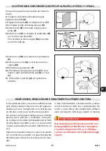
Per montare le apparecchiature in batteria (fi an-
co a fi anco) procedere nel modo indicato.

1) 

Sfi lare le manopole 

(A)

.

2) 

Svitare le viti 

(C)

 e smontare i cruscotti 

(B)

.

3) 

Svitare la vite 

(D)

 e ruotare la staff a 

(E)

 di 180° 

in senso antiorario.

4) 

Collegare le apparecchiature con le viti 

(F)

 e la 

staff a 

(G)

 (parte posteriore).

5) 

Collegare le apparecchiature con la vite 

(H) 

(forniita a corredo) e la staff a 

(E) 

(parte 

anteriore).

6) 

Rimontare i cruscotti 

(B)

 e le manopole 

(A)

 ad 

operazione ultimata.

Per le apparecchiature in batteria sono disponi-
bili, a richiesta, diversi kit di allestimento (vedi 
“catalogo generale”).

MONTAGGIO APPARECCHIATURE IN BATTERIA

180°

B

C

C

A

D

E

E

H

F

F

G

1

2

3

4

5

6

E

Summary of Contents for 0N1FR1G

Page 1: ...zung des Geräts müssen die Anleitungen aufmerksam durchgelesen werden Lire attentivement les instructions avant d installer et d utiliser l appareil Léanse atentamente las instrucciones antes de instalar y utilizar el aparato Il mancato rispetto delle istruzioni fa decadere la garanzia del fabbricante In the event of failure to comply with the instructions the manufacturer s warranty shall cease t...

Page 2: ...tergenti è obbligato rio utilizzare guanti in gomma maschera anti inalazione ed occhiali di protezione secondo le norme di sicurezza vigenti Cautela Avvertenza Non usare prodotti che contengono sostanze dannose e pericolose per la salute delle per sone solventi benzine ecc Cautela Avvertenza Prima di eseguire qualsiasi intervento disatti vare l alimentazione elettrica generale Importante Important...

Page 3: ...6 SICUREZZA 7 ISTRUZIONI E AVVERTENZE PER LA SICUREZZA 7 ISTRUZIONI E AVVERTENZE DI SICUREZZA PER L IMPATTO AMBIENTALE 8 USO E FUNZIONAMENTO 9 ISTRUZIONI E AVVERTENZE PER L USO E IL FUNZIONAMENTO 9 DESCRIZIONE COMANDI 9 ACCENSIONE E SPEGNIMENTO APPARECCHIATURA 10 FILTRAGGIO OLIO 11 RIPRISTINO APPARECCHIATURA 11 INATTIVITÀ PROLUNGATA DELL APPARECCHIATURA 12 ISTRUZIONI ED AVVERTENZE PER L USO 12 MAN...

Page 4: ...riginale italiano e vengono tradotte nelle altre lingue per soddi sfare le esigenze legislative e o commerciali La lettura di tali informazioni permetterà di evitare rischi alla salute e alla sicurezza delle persone e danni economici Conservare questo manuale per tutta la durata di vita dell apparecchiatura in un luogo noto e facilmente accessibile per averlo sempre a disposizione nel momento in c...

Page 5: ...udo b14 Tensione V b15 Frequenza Hz b16 Potenza elettrica assorbita W b17 Indicatore tensione collaudo b18 Data di costruzione C Targa gas collaudo c1 Tipo di gas c2 Pressione gas L installatore dovrà scegliere e applicare la targhetta A a fianco della targhetta di iden tificazione relativa al paese di utilizzo e dovrà contrassegnare a quale categoria appartiene Tipo A scarico standard Se il gas d...

Page 6: ...a di frittura realizzata in acciaio inox B Scarico fumi tipo A per evacuare i fumi generati dal bruciatore C Manopola regolazione temperatura per regolare la temperatura dell olio D Spia rete per segnalare l attivazione dell ali mentazione elettrica E Spia temperatura per segnalare la fase di riscaldamento dell olio contenuto nella vasca F Supporto appendicestello per appoggiare il cestello durant...

Page 7: ...ateria L illustrazione indica la posizione dei disposi tivi A Rubinetto alimentazione gas serve per aprire e chiudere il collegamento alla linea di alimentazione gas B Termocoppia di sicurezza blocca l alimen tazione del gas in caso di spegnimento della fiamma C Termostato di sicurezza per bloccare l alimentazione del gas in caso di surriscal damento DISPOSITIVI DI SICUREZZA 0 1FR1G 0 1FR3G 1 1FR2...

Page 8: ...hiatura B Pericolo generico prima di effettuare qual siasi tipo di intervento leggere attentamente il manuale C Pericolo generico durante il lavaggio dell apparecchiatura non dirigere getti d ac qua in pressione sulle parti interne D Pericolo generico richiama l attenzione sul rispetto delle norme Installare conforme mente alle normative in vigore ed utilizzare solo in ambienti bene areati E Peric...

Page 9: ...nze e danni economici Tutti gli interventi di manutenzione che richie dono una precisa competenza tecnica o parti colari capacità o qualifiche previste dalla legge devono essere eseguiti esclusivamente da per sonale debitamente qualificato e o abilitato e comunque con esperienza riconosciuta e acqui sita nel settore specifico di intervento Per mantenere l igiene e proteggere gli alimen ti lavorati...

Page 10: ...ener conto dei fattori di seguito indicati Emissioni nell atmosfera Scarichi dei liquidi Gestione dei rifiuti Contaminazione del suolo Uso delle materie prime e delle risorse naturali Problematiche locali relative all impatto ambientale A tale scopo il Fabbricante fornisce alcune indicazioni che dovranno essere considerate da tutti coloro che sono autorizzati ad interagire con l apparecchiatura ne...

Page 11: ...utilizzatori oltre ad impegnarsi a soddi sfare questi requisiti devono applicare tutte le norme di sicurezza e leggere con attenzio ne la descrizione dei comandi e la messa in servizio DESCRIZIONE COMANDI Sull apparecchiatura sono disposti i comandi per attivare le funzioni principali A Manopola regolazione temperatura per regolare l alimentazione del gas ed aumenta re e diminuire la temperatura d...

Page 12: ...denza della temperatura desiderata La spia temperatura D si accende per segnalare che l olio non è a temperatura di utilizzo A temperatura raggiunta la spia si spegne Spegnimento 1 Aprire il portello E 2 Premere e ruotare la manopola B in senso orario pos 5 per spegnere il bruciatore La spia pilota rimarrà accesa per successive riaccensioni del bruciatore 3 Premere e ruotare la manopola B in senso...

Page 13: ...zione ultimata 6 Richiudere il portello A Cautela Avvertenza Non disperdere olio nell ambiente ma eseguire lo smaltimento nel rispetto delle leggi vigenti del paese di utilizzo A B C C E D RIPRISTINO APPARECCHIATURA In caso di intervento del termostato di sicurezza è necessario ripristinare le condizioni iniziali di funzionamento dell apparecchiatura nel modo indicato 1 Lasciare raffreddare l olio...

Page 14: ...prima di utilizzare l apparecchiatura attende re che l olio sia in temperatura immergere il cestello lentamente per evitare la formazione di schiuma filtrare spesso l olio di frittura per eliminare i residui di lavorazione Importante Important Wichitig Important Importante Conservare l olio di frittura al freddo e al buio e filtrarlo frequentemente al fine di rallentar ne la progressiva degradazio...

Page 15: ...a termocoppia di sicurezza Verifica efficienza canna fumaria ed eventuale pulizia Verifica efficienza termostato di sicurezza Verificare efficienza impianto elettrico PULIZIA APPARECCHIATURA Se si considera che l apparecchiatura è utiliz zata per la preparazione di prodotti alimentari per l uomo è necessario prestare particolare cura a tutto ciò che riguarda l igiene e mante nere costantemente pul...

Page 16: ...idui di detergente 8 Risciacquare svuotare ed asciugare la vasca 9 Pulire gli accessori dopo l uso con uno sgrassante idoneo Si consiglia il lavaggio in lavastoviglie PULIZIA VASCA SUPPORTO CESTELLI E ACCESSORI Importante Important Wichitig Important Importante Quando viene utilizzata l acqua per la pulizia periodica assicurarsi che non vi siano tracce d acqua in vasca sugli accessori e nel con do...

Page 17: ... internet http www angelopo com Inconvenienti Cause Rimedi Odore di gas Fuga occasionale dovuta a spegnimento della fiamma Chiudere il rubinetto alimenta zione gas e aerare il locale La spia pilota non si accende Presenza d aria nelle tuba zioni dovuta a prolungata inattività Insistere più a lungo con l opera zione di accensione La spia pilota non rimane accesa La termocoppia non si è riscaldata a...

Page 18: ...nd safety goggles must be worn in accordance with the relevant safety regulations Caution Warning Never use products containing substances harmful or hazardous for health solvents petroleum spirits etc Caution Warning Before doing any work cut off the mains electricity supply Important Before it is put into service the system must be tested to check the operating conditions of every single compone...

Page 19: ...ON SIGNS 6 SAFETY 7 INSTRUCTIONS AND WARNINGS FOR SAFETY 7 SAFETY WARNINGS AND INSTRUCTIONS CONCERNING ENVIRONMENTAL IMPACT 8 USE AND OPERATION 9 INSTRUCTIONS AND WARNINGS FOR USE AND OPERATION 9 DESCRIPTION OF CONTROLS 9 SWITCHING THE APPLIANCE ON AND OFF 10 FILTERING OIL 11 RESETTING THE APPLIANCE 11 LENGTHY DOWNTIMES OF APPLIANCE 12 INSTRUCTIONS AND WARNINGS FOR USE 12 SERVICING 13 INSTRUCTIONS...

Page 20: ...ed by the manufac turer in the original language Italian and is translated into other languages to meet legal and or business requirements Reading this information will avoid health and safety risks to people and financial losses Keep this manual in a clearly identified safe pla ce throughout the working life of the appliance so that it will always be available when required for consultation The m...

Page 21: ... b15 Frequency Hz b16 Electricity power consumption W b17 Test voltage indicator b18 Date of construction C Testing gas plate c1 Type of gas c2 Gas pressure The installer must select the plate A and apply it alongside the nameplate relating to the country of use and must mark the rela tive appliance class Type A standard fume exhaust vent If the appliance is to be used with the same type of gas as...

Page 22: ...G I H Main Parts A Frying well in stainless steel B Fume exhaust vent Type A for removal of the fumes generated by the burner C Temperature regulator knob for regulating the oil temperature D Mains light indicates that the appliance is receiving electrical power E Temperature light to indicate that heating of the oil in the well is in progress F Basket hanger support to support the basket while fo...

Page 23: ...h applicable laws The illustration shows the position of the devices A Gas supply tap for turning the connection to the gas supply line on and off SAFETY DEVICES B Safety thermocouple cuts out the gas sup ply if the flame goes out C Safety thermostat cuts off the gas supply to the oven burner in case of oven overheating 0 1FR1G 0 1FR3G 1 1FR2G 1 1FR4G 0 1FR1G 1 1FR2G 0 1FR3G 0 1FR4G B B C C A ...

Page 24: ...late with manufacturer and appliance data B General hazard read the manual carefully before carrying out any procedure C General hazard when washing the appli ance do not point pressurised water jets at internal parts D General hazard all relevant regulations must be complied with Install in compli ance with the relevant regulations and use in well ventilated premises only E General hazard all rel...

Page 25: ...maintenance work that requires precise technical expertise or particular skills or qualifi cations for legal reasons should be carried out by suitably trained and or qualified staff and in any case with recognised experienced gained in the specific field of intervention To maintain hygiene and protect the food processed from all forms of contamination all elements in direct or indirect contact wit...

Page 26: ...luents Waste management Soil contamination Use of raw materials and natural resources Local problems relating to environmental impact For this purpose the manufacture supplies information which must be considered by all those authorised to interact with the appliance during its expected lifetime in order to prevent environmental impact All packaging materials must be disposed of in accordance with...

Page 27: ...l as taking care to meet these require ments users must also implement all safety regulations and read the description of the controls and the start up procedure carefully DESCRIPTION OF CONTROLS The appliance is fitted with the controls for use of its main functions A Temperature regulator knob regulates the gas supply to increase or decrease the oil temperature B Burner control knob lights and t...

Page 28: ...the tem perature required The temperature light D comes on to indicate that the oil is not at the working temperature The light goes out when the temperature is reached Turning off 1 Open the hatch E 2 Press and turn the knob B clockwise pos 5 to turn off the burner The pilot light will remain on to allow the burner to be re lit 3 Press and turn the knob B clockwise pos 6 to turn off the pilot lig...

Page 29: ...the tap C on completion of the opera tion 6 Close the hatch A Caution Warning Do not dump oil in the environment dispose of it in accordance with the laws in force in the country of use A B C C E D RESETTING THE APPLIANCE If the safety thermostat is tripped the applian ce has to be restored to the initial working conditions as follows 1 Allow the oil to cool to 30 40 C 2 Open the hatch A 3 Press t...

Page 30: ...recommended for fryers Melt solid fats in a separate container to avoid damaging the appliance Do not use the appliance until the oil is at working temperature Lower the basket slowly to prevent foaming Filter the frying oil often to remove working residues Important Store frying oil in the dark and filter it often to slow down its gradual degradation The use of degraded oil for frying constitutes...

Page 31: ... mocouple A check on the efficiency of the flues cleaning them if necessary Check that the safety thermostat is working correctly Check that the electrical system is in good working order CLEANING INSTRUCTIONS Since the appliance is used for preparing foods for human consumption special care must be paid to everything relating to hygiene and the appliance and the entire surrounding envi ronment mu...

Page 32: ... remove the detergent residues 8 Rinse empty and dry the pan 9 After use clean the accessories with a suitable grease remover product If possible wash in the dishwasher CLEANING THE WELL BASKET SUPPORT AND ACCESSORIES Important When using water for routine cleaning check that there are no traces of water left in the well on the accessories and in the drain line before refilling with oil A Take spe...

Page 33: ...tion of the website http www angelopo com Faults Causes Remedies Smell of gas Occasional leak because flame has gone out Turn off the gas supply tap and ventilate the room The pilot light does not ignite Air in pipelines due to long period out of use Make more attempts to light the flame The pilot light goes out The thermocouple has not warmed up enough Make more attempts to light the flame The pi...

Page 34: ...chuhe Atemschutzmaske und Schutzbrille zu tragen sind Vorsicht Achtung Verwenden Sie keine Produkte die Stoffe en thalten welche für die menschliche Gesun dheit schädlich und gefährlich sind Lösemit tel Benzin usw Vorsicht Achtung Vor Ausführung irgendeines Eingriffs die Hauptstromversorgung unterbrechen Wichitig Vor der Inbetriebnahme muss ein Testlauf der Anlage durchgeführt werden um den Betrie...

Page 35: ...NGEN UND WARNHINWEISE FÜR DIE SICHERHEIT 7 ANLEITUNGEN UND SICHERHEITSANWEISUNGEN FÜR DIE UMWELTAUSWIRKUNGEN 8 GEBRAUCH UND BETRIEB 9 ANWEISUNGEN UND WARNHINWEISE FÜR DIE BEDIENUNG UND BETRIEB 9 BESCHREIBUNG DER BEDIENELEMENTE 9 EIN UND AUSSCHALTEN DES GERÄTS 10 ÖLFILTERUNG 11 RÜCKSETZEN DES GERÄTS 11 LÄNGERER STILLSTAND DES GERÄTS 12 ANWEISUNGEN UND WARNHINWEISE FÜR DIE BEDIENUNG 12 WARTUNG 13 AN...

Page 36: ...nisch bereitgestellt und in andere Sprachen übersetzt um den ge setzlichen bzw handelstechnischen Bedürfnis sen gerecht zu werden Die Lektüre dieser Informationen ermöglicht die Vermeidung von Gesundheits und Sicher heitsrisiken für Personen und wirtschaftlichen Schäden Bewahren Sie dieses Handbuch für die gesamte Lebensdauer des Gerätes an einem bekannten und leicht zugänglichen Ort auf damit es ...

Page 37: ...jahr C Testgasschild c1 Gastyp c2 Gasdruck Der Installateur muss das geeignete Schild A auswählen neben dem Schild für das Benutzer land aufbringen und mit dem Kennzeichen für die betreffende Kategorie versehen Typ A Standardabzug Wenn das verwendete Gas mit dem überein stimmt welches der Hersteller beimTestlauf verwendet hat so ist es für die Abnahme ausrei chend das Schild C zu entfernen und die...

Page 38: ...E F G I H Hauptorgane A Frittierbecken aus Edelstahl B Rauchabzug Typ A zum Abführen der vom Brenner erzeugten Rauchgase C SchalterTemperatureinstellung zum Einstel len der Öltemperatur D Kontrollleuchte Stromzufuhr zur Anzeige der Stromzufuhr E KontrollleuchteTemperatur zeigt die Phase der Erhitzung des im Becken enthaltenen Öls an F Korbaufhängergestell pzum Abstellen des Korbs beim Abtropfen de...

Page 39: ...tegriert werden Die Abbildung zeigt die Anordnung der Sicher heitsvorrichtungen A Gashahn um die Leitung für die Gaszufuhr zu öffnen oder abzusperren SICHERHEITSVORRICHTUNGEN B Sicherheits Thermoelement stellt die Gas abfuhr ab wenn die Flamme erlischt C Sicherheitsthermostat bricht die Gaszufuhr zum Brenner Ofen bei Ofen Überhitzung 0 1FR1G 0 1FR3G 1 1FR2G 1 1FR4G 0 1FR1G 1 1FR2G 0 1FR3G 0 1FR4G ...

Page 40: ...penschild mit Angabe des Herstellers und der Gerätekenndaten B Allgemeine Gefahr Vor Ausführung irgend eines Eingriffs zuerst das Handbuch aufmerk sam lesen C Allgemeine Gefahr Beim Waschen des Geräts den Wasserstrahl nicht direkt auf die inneren Teile richten D Allgemeine Gefahr Fordert zur Beachtung der Vorschriften auf Im Falle der Missach tung der Vorschriften für die Installation und Inbetrie...

Page 41: ...h in seiner Nähe befinden beschädigen und wirt schaftliche Schäden verursachen Alle Wartungseingriffe die technisches Fach wissen oder spezielle Fähigkeiten oder eine gesetzlich vorgeschriebene Ausbildung erfor dern dürfen ausschließlich von entsprechend ausgebildetem bzw zugelassenem Personal mit nachweislicher Erfahrung in dem betreffendem Bereich durchgeführt werden Aus hygienischen Gründen und...

Page 42: ...er signifikanten Auswirkungen auf die Umwelt müssen die nach stehenden Faktoren berücksichtigen Emissionen in die Atmosphäre Abwässer Abfallwirtschaft Bodenverunreinigung Nutzung der Rohstoffe und natürlichen Res sourcen Ortsgebundene Probleme in Hinblick auf die Umweltbelastung Zu diesem Zweck gibt der Hersteller einige Hinweise die von jedem der zur Interaktion mit dem Gerät während seines vorge...

Page 43: ...tzer müssen diese Vorschriften und außerdem alle Sicherheitsvorschriften be achten Sie müssen ferner die Beschreibung der Bedieneinrichtungen und der Inbetrieb nahme aufmerksam lesen BESCHREIBUNG DER BEDIENELEMENTE Das Gerät ist mit Bedienelementen zur Aktivie rung der wichtigsten Funktionen ausgestattet A SchalterTemperatureinstellung regelt die Gaszufuhr zur Erhöhung und Senkung der Öltemperatur...

Page 44: ...rehen um die gewünschte Temperatur einzustellen Das Erleuchten der Kontrollleuchte D zeigt an dass das Öl nicht die vorgegebene Betriebstem peratur hat bei erreichter Temperatur erlischt die Kontrollleuchte Abschaltung 1 Öffnen Sie die Klappe E 2 Drücken und drehen Sie den Schalter B im Uhrzeigersinn Pos 5 um den Brenner auszu schalten Der Zündflammenbrenner bleibt für die folgen den Zündungen des...

Page 45: ... C wieder zudrehen 6 Schließen Sie die Klappe A Vorsicht Achtung Das Öl vorschriftsmäßig entsprechend den im Benutzungsland geltenden Bestimmungen entsorgen A B C C E D RÜCKSETZEN DES GERÄTS Wenn der Sicherheitsthermostat anspricht muss das Gerät in der angegebenen Weise wieder in den normalen Betriebszustand versetzt werden 1 Das Öl um 30 40 C abkühlen lassen 2 Öffnen Sie die Klappe A 3 Den Taste...

Page 46: ...le für Friteusen benutzen Zum Schmelzen von Hartfett ein separates Gefäß verwenden um das Gerät nicht zu beschädigen Vor Benutzung des Geräts warten bis das Öl die richtige Temperatur erreicht hat Den Korb langsam eintauchen um eine Schaumbildung zu vermeiden Das Frittieröl oft filtern um die Frit tierrückstände zu beseitigen Wichitig Das Frittieröl im Kühlen und im Dunkeln aufbewahren und häufig ...

Page 47: ...t der Anlage Überprüfung der Funktionsfähigkeit des Sicherheits Thermoelements Prüfung der Wirksamkeit und ggf Reinigung des Abzugsrohrs und der Luftöffnungen Funktionsprüfung des Sicherheitsthermostats Funktionsprüfung der elektrischen Anlage REINIGUNG DES GERÄTS Da das Gerät zur Zubereitung von Speisen für den Menschen eingesetzt wird ist besondere Sorgfalt auf die Hygiene geboten Das Gerät und ...

Page 48: ...leeren und trocknen 9 Die Zubehörteile nach dem Gebrauch mit einem geeigneten Fettlöser reinigen Wir empfehlen die Reinigung im Geschirrspüler REINIGUNG DES BECKENS DES KORBGESTELLS UND DES ZUBEHÖRS Wichitig Wenn zur regelmäßigen Reinigung Wasser verwendet wird muss man vor dem erneuten Einfüllen des Öls sicherstellen dass sich kei ne Wasserreste im Becken auf dem Zubehör und in der Ablassleitung ...

Page 49: ...chen Lösungen Gasgeruch Beim Löschen der Flamme entstehender gelegentlicher Gasaustritt Schließen Sie den Gashahn und lüften Sie den Raum Der Zündflammenbrenner lässt sich nicht einschalten Durch längeren Stillstand hervorgerufene Luftblasen in den Leitungen Versuchen Sie erneut und länger den Zündungsvorgang zu starten Der Zündflammenbrenner bleibt nicht eingeschaltet Das Thermoelement ist nicht ...

Page 50: ...ion conformément aux normes de sécurité en vigueur Attention Ne pas utiliser de produits qui contiennent des substances dangereuses pour la santé des personnes solvants essences etc Important Le branchement doit être fait par du per sonnel autorisé et qualifié conformément aux lois en vigueur à ce sujet en utilisant le matériel approprié et prescrit Attention Avant toute intervention couper l alim...

Page 51: ... LA SÉCURITÉ 7 INSTRUCTIONS ET MISES EN GARDE DE SÉCURITÉ POUR L IMPACT ENVIRONNEMENTAL 8 UTILISATION ET FONCTIONNEMENT 9 INSTRUCTIONS ET AVERTISSEMENTS POUR L UTILISATION ET FONCTIONNEMENT 9 DESCRIPTION DES COMMANDES 9 ALLUMAGE ET EXTINCTION DE L APPAREIL 10 FILTRACIÓN ACEITE 11 RÉTABLISSEMENT DES FONCTIONS DE L APPAREIL 11 INUTILISATION PROLONGÉE DE L APPAREIL 12 INSTRUCTIONS ET AVERTISSEMENTS P...

Page 52: ...ue originale italien et sont tradui tes dans les autres langues afin de satisfaire les exigences législatives et ou commerciales La lecture de ces informations permettra d évi ter les risques pour la santé et la sécurité des personnes et dommages économiques Conserver ce manuel pour toute la durée de vie de l appareil dans un lieu connu et facile ment accessible pour l avoir toujours à disposi tio...

Page 53: ... essai b14 Tension V b15 Fréquence Hz b16 Puissance électrique absorbée W b17 Indicateur de tension d essai b18 Date de fabrication C Plaque du gaz d essai c1 Type de gaz c2 Pression du gaz L installateur devra choisir et appliquer la plaque A à côté de la plaque d identification relative au pays d utilisation et devra reporter la catégorie d appartenance Type A évacua tion standard Si le gaz d ut...

Page 54: ...Cuve de friture en acier inox B Évacuation des fumées Type A pour éva cuer les fumées générées par le brûleur C Manette de réglage de la température pour régler la température de l huile D Voyant de réseau pour signaler l activation de l alimentation électrique E Voyant de la température pour signaler la phase de réchauffement de l huile contenue dans la cuve F Support porte panier pour poser le p...

Page 55: ...pos L illustration indique la position des dispositifs A Robinet d alimentation du gaz pour ouvrir et fermer le raccordement à la ligne d alimen tation du gaz DISPOSITIFS DE SÉCURITÉ B Thermocouple de sécurité il bloque l ali mentation du gaz en cas d extinction de la flamme C Thermostat de sécurité coupe l alimenta tion en gaz vers le brûleur du four en cas de surchauffe du four 0 1FR1G 0 1FR3G 1...

Page 56: ...ant et de l appareil B Risque générique avant tout type d inter vention lire attentivement ce manuel C Risque générique pendant le lavage de l appareil ne pas diriger de jets d eau sous pression sur les pièces intérieures D Risque générique rappelle l attention sur le respect des normes Installer conformé ment aux normes en vigueur et n utiliser que dans des pièces bien aérées E Risque générique r...

Page 57: ...enance qui nécessitent une compétence technique précise ou de particulières capacités ou qualifications prévues par la loi doivent être effectuées exclu sivement par un personnel dûment qualifié et ou habilité et possédant en tout cas une ex périence reconnue et acquise dans le secteur spécifique d intervention Pour maintenir l hygiène et protéger les ali ments de tous les phénomènes de contami na...

Page 58: ... suivants Émissions dans l atmosphère Évacuations des liquides Gestion des déchets Contamination du sol Utilisation des matières premières et des res sources naturelles Problèmes locaux relatifs à l impact environ nemental Pour cela le fabricant fournit quelques indi cations qui devront être considérées par tous ceux autorisés à interagir avec l appareil au cours de sa vie prévue pour prévenir l i...

Page 59: ...t s engager à satis faire ces conditions doivent appliquer toutes les normes de sécurité et lire attentivement la description des commandes et la mise en marche DESCRIPTION DES COMMANDES Sur l appareil sont disposées les commandes pour activer les fonctions principales A Manette de réglage de la température règle l alimentation du gaz pour augmenter et dimi nuer la température de l huile B Manette...

Page 60: ...de la température désirée Le voyant de la température D s allume pour signaler que l huile n est pas à la température d utilisation Lorsque la température est atteinte le voyant s éteint Extinction 1 Ouvrir la porte E 2 Presser et tourner la poignée B en sens horaire pos 5 pour éteindre le brûleur La veilleuse pilote restera allumée pour des rallumages successifs du brûleur 3 Presser et tourner la...

Page 61: ...er le robinet C 6 Refermer la porte A Attention Ne pas écouler l huile dans l atmosphère mais effectuer son élimination conformément aux lois en vigueur dans le pays d utilisation A B C C E D RÉTABLISSEMENT DES FONCTIONS DE L APPAREIL Dans le cas d intervention du thermostat de sécurité il faut rétablir les conditions initiales de fonctionnement de l appareil dans le mode indiqué 1 Laisser refroid...

Page 62: ...art pour fondre les graisses solides afin de ne pas endommager l appareil Avant d utiliser l appareil attendre que l huile ait atteint la température Plonger le panier lentement pour éviter la formation d écume Filtrer souvent l huile de friture pour éliminer les résidus Important Conserver l huile de friture dans un endroit frais et à l abri de la lumière La filtrer sou vent pour réduire sa vites...

Page 63: ...ouple de sécurité Vérification du bon fonctionnement de la mi tre des prises d air et si nécessaire nettoyage Vérifier l efficacité du thermostat de sécurité Vérifier le bon fonctionnement de l installa tion électrique NETTOYAGE DE L APPAREIL Étant donné que l appareil est utilisé pour la préparation de produits alimentaires pour l homme il faut faire attention à tout ce qui concerne l hygiène l a...

Page 64: ... 8 Rincer vider et essuyer le bac 9 Nettoyer les accessoires après leur utilisation avec un dégraissant approprié Le lavage en lave vaisselle est conseillé NETTOYAGE DE LA CUVE DU SUPPORT DES PANIERS ET DES ACCESSOIRES Important Après le lavage périodique à l eau s assurer qu il n y a plus de traces d eau dans la cuve sur les accessoires et dans le conduit d éva cuation avant de remettre l huile A...

Page 65: ...n contacts du site internet http www ange lopo com Inconvénients Causes Solutions Odeur de gaz Fuite occasionnelle due à l extinction de la flamme Fermer le robinet d alimentation du gaz et aérer la pièce La veilleuse pilote ne s allu me pas Présence d air dans les tu yauteries due à une inactivité prolongée Insister avec l allumage La veilleuse pilote ne reste pas allumée Le thermocouple n est pa...

Page 66: ...n goma mascarilla contra inhalaciones y gafas de protección en con formidad con lo dispuesto por las normas vi gentes sobre seguridad Precaución advertencia No usar productos que contengan sustan cias nocivas y o peligrosas para la salud de las personas disolventes bencinas etc Precaución advertencia Antes de realizar cualquier operación se de berá desconectar la alimentación eléctrica general Imp...

Page 67: ...SEGURIDAD 7 INSTRUCCIONES Y ADVERTENCIAS PARA LA SEGURIDAD 7 INSTRUCCIONES Y ADVERTENCIAS DE SEGURIDAD PARA EL IMPACTO AMBIENTAL 8 USO Y FUNCIONAMIENTO 9 INSTRUCCIONES Y ADVERTENCIAS PARA EL USO Y FUNCIONAMIENTO 9 DESCRIPCIÓN DE LOS MANDOS 9 ENCENDIDO Y APAGADO DEL APARATO 10 FILTRACIÓN ACEITE 11 REACTIVACIÓN APARATO 11 PERÍODO PROLONGADO DE INACTIVIDAD DEL EQUIPO 12 INSTRUCCIONES Y ADVERTENCIAS P...

Page 68: ...ioma original italiano y está traducida en los demás idiomas para satisfacer necesidades comerciales y o requisitos estable cidos en la Ley La lectura de esta información permitirá evitar riesgos a la salud y la seguridad de las personas y daños económicos Conservar este manual durante toda la vida útil del equipo en un lugar conocido y fácil mente accesible a fin de tenerlo a disposición cuando s...

Page 69: ... Hz b16 Potencia eléctrica absorbida W b17 Indicador tensión de prueba b18 Fecha de fabricación C Placa gas prueba de funcionamiento c1 Tipo de gas c2 Presión del gas El instalador deberá seleccionar y fijar la placa A al lado de la placa de identificación relativa al país de uso y deberá marcar la categoría a la cual pertenece Tipo A descarga estándar Si el gas de uso es el mismo usado por el fa ...

Page 70: ...s A Cuba de freído fabricada en acero inox B Salida de humos Tipo A para evacuar los humos generados por el quemador C Mando de regulación temperatura para regular la temperatura del aceite D Testigo red para señalar la activación de la alimentación eléctrica E Testigo temperatura para señalar la fase de calentamiento del aceite presente en la cuba F Soporte enganche para cesto para colocar el ces...

Page 71: ...materia La ilustración indica la posición de los dispo sitivos A Grifo alimentación gas para abrir y cerrar el enlace de la línea de alimentación del gas B Termopar de seguridad bloquea la alimen tación del gas al apagarse la llama C termostato de seguridad corta el sumini stro de gas al quemador del horno en caso de sobrecalentamiento del horno DISPOSITIVOS DE SEGURIDAD 0 1FR1G 0 1FR3G 1 1FR2G 1 ...

Page 72: ...rato B Peligro genérico antes de efectuar cual quier tipo de intervención leer atentamente el manual C Peligro genérico durante el lavado del aparato no dirigir chorros de agua a presión hacia sus partes internas D Peligro genérico tiene por objeto recordar la necesidad de respetar las normas Instalar en conformidad con lo dispuesto por la nor mativa vigente y utilizar sólo en ambientes adecuadame...

Page 73: ...eran una competencia técnica específi ca o especiales capacidades o cualificaciones previstas por la Ley tienen que ser realizadas exclusivamente por personal debidamente cua lificado y o habilitado y de todas formas con experiencia reconocida y adquirida en el sector específico de intervención Para mantener la higiene y proteger los alimen tos trabajados respecto de cualquier fenómeno de contamin...

Page 74: ...a Descargas de líquidos Gestión de residuos Contaminación del suelo Uso de materias primas y de recursos natu rales Problemáticas locales relativas al impacto ambiental Es por ello que con el fin de prevenir el impacto ambiental el fabricante entrega algunas instruc ciones que deberán ser respetadas por todas las personas autorizadas para interactuar con el aparato en el arco de su vida útil Todos...

Page 75: ...ta y eficaz Los usuarios además de obligarse a cum plir estos requisitos deben aplicar todas las normas de seguridad y leer con atención la descripción de los mandos y de la puesta en servicio DESCRIPCIÓN DE LOS MANDOS Para activar las funciones principales en el equipo se han instalado los siguientes mandos A Mando de regulación temperatura regula la alimentación del gas a fin de aumentar o reduc...

Page 76: ...espondencia con la temperatura deseada El testigo temperatura D se enciende para indicar que el aceite no ha alcanzado la temperatura prevista Una vez alcanzada dicha temperatura este testigo se apaga Apagado 1 Abrir la portezuela E 2 Presione y gire el selector B en sentido horario pos 5 para apagar el quemador El testigo piloto permanecerá encendido para los sucesivos encendidos del quemador 3 P...

Page 77: ...aceite en el ambiente Su elimi nación deberá efectuarse de conformidad con lo establecido por las normas vigentes en el país de uso A B C C E D REACTIVACIÓN APARATO En caso de intervención del termostato de seguridad será necesario restablecer las condi ciones iniciales de funcionamiento del aparato procediendo para ello de la manera que a continuación se indica 1 Dejar enfriar el aceite en la med...

Page 78: ...íficos para freidoras A fin de no dañar el aparato utilizar un recipiente separado para fundir las grasas sólidas Esperar que el aceite alcance la temperatura requerida antes de utilizar el aparato Sumergir el cesto lentamente a fin de evitar la formación de espuma Filtrar frecuentemente el aceite de freído para eliminar los residuos de freidura Importante Conservar el aceite de freído en frío y e...

Page 79: ...iguientes operaciones Controlar presión gas y hermeticidad del sistema Controlar la eficacia del termopar de seguri dad Control de la eficiencia de la chimenea de las tomas de aire y eventual limpieza Control de la eficiencia del termostato de seguridad Controlar la eficiencia del sistema eléctrico LIMPIEZA APARATO Atendida la circunstancia de que el equipo es utilizado para la preparación de prod...

Page 80: ...tuar el lavado en lavavajillas LIMPIEZA DE CUBA SOPORTE CESTOS Y ACCESORIOS Importante Important Wichitig Important Importante En caso de utilizar agua para efectuar la lim pieza periódica antes de reintroducir el acei te controlar la ausencia de trazas de agua en la cuba en los accesorios y en el conducto de evacuación A Precaución advertencia No usar productos que contengan sustancias nocivas y ...

Page 81: ...e indican en la sección de contac tos del sitio web http www angelopo com Inconvenientes Causas Remedios Olor de gas Fuga ocasional debida al apagado de la llama Cerrar el grifo de alimentación del gas y ventilar el local El testigo piloto no se enciende Presencia de aire en las tuberías debida a un período prolongado de inactividad Insistir con la operación de en cendido El testigo piloto no se m...

Page 82: ......

Page 83: ...r et d utiliser l appareil Léanse atentamente las instrucciones antes de instalar y utilizar el aparato Il mancato rispetto delle istruzioni fa decadere la garanzia del fabbricante In the event of failure to comply with the instructions the manufacturer s warranty shall cease to apply Die Missachtung der Anleitungen hat den Verfall der vom Hersteller gewährten Garantie zur Folge Le non respect des...

Page 84: ......

Page 85: ... SICUREZZA 5 ISTRUZIONI E AVVERTENZE DI SICUREZZA PER L IMPATTO AMBIENTALE 5 MANUTENZIONE 6 ISTRUZIONI ED AVVERTENZE PER LA MANUTENZIONE 6 CONTROLLO PRESSIONE GAS 6 GUASTI 7 RICERCA GUASTI 7 MOVIMENTAZIONE E INSTALLAZIONE 7 ISTRUZIONI E AVVERTENZE PER LA MOVIMENTAZIONE E INSTALLAZIONE 7 IMBALLO E DISIMBALLO 7 TRASPORTO 7 MOVIMENTAZIONE E SOLLEVAMENTO 8 INSTALLAZIONE APPARECCHIATURA 8 VENTILAZIONE ...

Page 86: ... 1FR1G 1 1FR2G 14 REGOLAZIONE ARIA PRIMARIA BRUCIATORE 0 1FR3G 1 1FR4G 15 SOSTITUZIONI PARTI 15 ISTRUZIONI E AVVERTENZE PER LA SOSTITUZIONE PARTI 15 SOSTITUZIONE UGELLO BRUCIATORE 15 SOSTITUZIONE UGELLO SPIA PILOTA 16 SOSTITUZIONE COMPONENTI GRUPPO SPIA PILOTA 0 1FR1G 1 1FR2G 16 SOSTITUZIONE COMPONENTI GRUPPO SPIA PILOTA 0 1FR3G 1 1FR4G 17 DISMISSIONE DEMOLIZIONE E SMALTIMENTO APPARECCHIATURA 17 A...

Page 87: ...rnite dal Fabbrican te nella propria lingua originale italiano e ven gono tradotte nelle altre lingue per soddisfare le esigenze legislative e o commerciali La lettura di tali informazioni permetterà di evi tare rischi alla salute e alla sicurezza delle perso ne e danni economici Conservare questo manuale per tutta la durata di vita dell apparecchiatura in un luogo noto e facilmente accessibile pe...

Page 88: ...Targa di identificazione b1 Modello apparecchiatura b2 Tipo di personalizzazione b3 Identificazione Fabbricante b4 Numero di matricola b5 Indice di protezione b6 Marcatura CE di conformità b7 Norma di riferimento b8 Numero certificato CE b9 Tipo famiglia prodotto b10 Tipo di gas b11 Potenza dichiarata kW b12 Consumo gas b13 Indicatore gas collaudo b14 Tensione V b15 Frequenza Hz b16 Potenza elettr...

Page 89: ...ONE Vedi paragrafo SEGNALI DI SICUREZZA E INFORMAZIONE del manuale Istruzioni per l utilizzatore ACCESSORI A RICHIESTA Vedi paragrafo ACCESSORI A RICHIESTA del manuale Istruzioni per l utilizzatore SICUREZZA ISTRUZIONI E AVVERTENZE PER LA SICUREZZA Vedi paragrafo ISTRUZIONI E AVVERTENZE PER LA SICUREZZA del manuale Istruzioni per l utilizzatore ISTRUZIONI E AVVERTENZE DI SICUREZZA PER L IMPATTO AM...

Page 90: ...intervento di manutenzione l operatore sia sempre in grado di poter controllare che la spina sia di sinserita dalla presa di corrente Ogni 100 ore di esercizio fare eseguire da opera tori esperti e autorizzati le seguenti operazioni Controllo pressione gas e tenuta impianto Verifica efficienza termocoppia di sicurezza Verifica efficienza canna fumaria ed eventua le pulizia Verifica efficienza term...

Page 91: ...tenimento degli in gombri anche in funzione del tipo di trasporto adottato Per facilitare il trasporto la spedizio ne può essere eseguita con alcuni componenti smontati ed opportunamente protetti e imbal lati Sull imballo sono riportate tutte le informazioni necessarie ad effettuare il carico e lo scarico In fase di disimballo controllare l integrità e l e satta quantità dei componenti Il material...

Page 92: ...rogetto ge nerale Prima di iniziare tali fasi oltre alla definizione della zona di installazione chi è autorizzato ad eseguire queste operazioni dovrà se necessario attuare un piano di sicurezza per salvaguardare l incolumità delle persone direttamente coinvolte ed applicare in modo rigoroso tutte le leggi con particolare riferimento a quelle sui cantieri mobili La zona di installazione deve esser...

Page 93: ...enso antiorario 4 Collegare le apparecchiature con le viti F e la staffa G parte posteriore 5 Collegare le apparecchiature con la vite H forniita a corredo e la staffa E parte anteriore 6 Rimontare i cruscotti B e le manopole A ad operazione ultimata Per le apparecchiature in batteria sono disponi bili a richiesta diversi kit di allestimento vedi catalogo generale MONTAGGIO APPARECCHIATURE IN BATT...

Page 94: ...traverso un controllo generale che non vi siano fughe di gas Per effettuare l allacciamento collegare il tubo di rete con il tubo di attacco dell apparecchiatura interponendo un rubinetto di intercettazione A per interrompere quando necessario l alimen tazione del gas la posizione del tubo di attacco dell apparecchiatura varia in base al modello vedi schemi d allacciamento in fondo al manua le Imp...

Page 95: ... interruttore sezionatore A alla morsettiera E dell apparecchiatura come indicato in figura e nello schema elettrico in fondo al manuale Utilizzare un cavo flessibile con caratteristiche non inferiori al tipo H07RN F e con temperatu ra di utilizzo di almeno 80 C Importante In fase di allacciamento fare attenzione al col legamento dei cavi di neutro e di terra se non è effettuato correttamente il b...

Page 96: ... del bruciatore 4 Verificare e se necessario regolare la pressione e la portata del gas al minimo e al massimo vedi pag 13 14 5 Verificare il corretto funzionamento della termocoppia di sicurezza 6 Verificare che non vi siano perdite di gas 7 Verificare che le targhette siano compilate con le indicazioni del gas relativo al paese di utilizzo Effettuato il collaudo se necessario addestrare opportun...

Page 97: ...are questa regolazione è ne cessario verificare che la pressione del gas di alimentazione sia conforme al valore della pressione nominale relativa allo stesso tipo di gas vedi tabella in fondo al manuale Eseguire questa operazione nel modo indicato su entrambe le elettrovalvole gas Metano 1 Chiudere il rubinetto alimentazione gas 2 Aprire il portello A 3 Svitare il tappo D 4 Avvitare a fondo la vi...

Page 98: ... Riaprire il rubinetto alimentazione gas 7 Accendere il bruciatore e regolare la vite E fino a leggere sul manometro la pressione indicata nella tabella iniettori in fondo al ma nuale 8 Verificare la stabilità della fiamma Dopo la re golazione sigillare la vite con vernice 9 Spegnere il bruciatore scollegare il manome tro e ripristinare le condizioni iniziali ad opera zione ultimata A C B D E Gas ...

Page 99: ...arechiudereilrubinet toalimentazionegasedimpedirel accessoatutti i dispositivi che potrebbero se attivati provoca re condizioni di pericolo inatteso causando dan niallasicurezzaeallasalutedellepersone Qualora sia necessario sostituire dei compo nenti usurati utilizzare esclusivamente dei ri cambi originali Si declina ogni responsabilità per danni a persone o componenti derivanti dall impiego di ri...

Page 100: ...entazione gas 2 Aprire il portello A 3 Svitare le viti B per smontare la protezione C 4 Scollegare il tubo alimen tazione gas E 5 Svitare la termocoppia D SOSTITUZIONE UGELLO SPIA PILOTA SOSTITUZIONE COMPONENTI GRUPPO SPIA PILOTA 0 1FR1G 1 1FR2G 6 Scollegare il cavo P 7 Svitare le viti F e smontare il gruppo spia pilota G 8 Svitare le viti H e sostituire la candeletta L e o il corpo spia pilota M ...

Page 101: ...TURA In fase di dismissione è necessario effettuare una serie di interventi per fare in modo che l apparec chiatura ed i suoi componenti non costituiscano un intralcio e non siano facilmente accessibili Per evitare che l apparecchiatura possa costituire pericoli per le persone e l ambiente è necessa rio scollegare e rendere inutilizzabili tutte le fonti di alimentazione elettrica ecc e scaricare t...

Page 102: ......

Page 103: ...D WARNINGS FOR SAFETY 5 SAFETY WARNINGS AND INSTRUCTIONS CONCERNING ENVIRONMENTAL IMPACT 5 SERVICING 6 INSTRUCTIONS AND WARNINGS FOR SERVICING 6 CHECKING GAS PRESSURE 6 FAULT 7 TROUBLESHOOTING 7 HANDLING AND INSTALLATION 7 INSTRUCTIONS AND WARNINGS FOR HANDLING AND INSTALLATION 7 PACKAGING AND UNPACKING 7 TRANSPORT 7 HANDLING AND LIFTING 8 INSTALLATION OF THE APPLIANCE 8 ROOM VENTILATION 8 ASSEMBL...

Page 104: ...FR1G 1 1FR2G 14 ADJUSTING BURNER PRIMARY AIR 0 1FR3G 1 1FR4G 15 REPLACING PARTS 15 INSTRUCTIONS AND WARNING FOR REPLACING PARTS 15 REPLACEMENT OF THE BURNER NOZZLE 15 REPLACEMENT OF THE PILOT LIGHT INJECTOR 16 REPLACEMENT OF PILOT LIGHT UNIT COMPONENT 0 1FR1G 1 1FR2G 16 REPLACEMENT OF PILOT LIGHT UNIT COMPONENTS 0 1FR3G 1 1FR4G 17 EQUIPMENT DECOMMISSIONING DEMOLITION AND DISPOSAL 17 ALLEGATI ANNEX...

Page 105: ...ns to the letter This information is provided by the manufac turer in the original language Italian and is translated into other languages to meet legal and or business requirements Reading this information will avoid health and safety risks to people and financial losses Keep this manual in a clearly identified safe place throughout the working life of the appli ance so that it will always be ava...

Page 106: ...model b2 Type of customisation b3 manufacturer identification b4 Serial number b5 Protection class b6 EC conformity mark b7 Reference standard b8 EC certificate number b9 Product family type b10 Type of gas b11 Rated power kW b12 Gas consumption b13 Testing gas indicator frame b14 Voltage V b15 Frequency Hz b16 Electricity power consumption W b17 Test voltage indicator b18 Date of construction C T...

Page 107: ...GNS See paragraph SAFETY AND INFORMATION SI GNS of the User instructions manual OPTIONAL ACCESSORIES See paragraph OPTIONAL ACCESSORIES of the User instructions manual SAFETY INSTRUCTIONS AND WARNINGS FOR SAFETY See paragraph INSTRUCTIONS AND WARNINGS FOR REGULATIONS of the User instructions ma nual SAFETY WARNINGS AND INSTRUCTIONS CONCERNING ENVIRONMENTAL IMPACT See paragraph SAFETY WARNINGS AND ...

Page 108: ...wer outlet Every 100 working hours have skilled autho rised personnel carry out the following opera tions A check on the gas pressure and system tight ness A check on the efficiency of the safety ther mocouple A check on the efficiency of the flues cleaning them if necessary Check that the safety thermostat is working correctly Check that the electrical system is in good working order To carry out...

Page 109: ... and as appropriate to the type of transport used To simplify transport some components may be removed and suitably protected and packed for transport The packaging carries all information necessary for loading and unloading When unpacking check that all components are present in the correct quantities and are unda maged The packaging material must be properly dispo sed of in accordance with legal...

Page 110: ...eral layout Befo re starting these stages as well as deciding the place of installation if necessary the person authorised to carry out these operations must organise a safety plan to protect the people di rectly involved and he must also ensure strict compliance with all legal requirements espe cially those relating to mobile work sites The place of installation must have all the con nections nee...

Page 111: ...4 Connect the appliance using the screws F and the bracket G rear part of the applian ce fig 4 5 5 Connect the appliance using the screws H supplied and the bracket E front part of the appliance fig 6 6 Replace the control panels B and the knobs A on completion of the operation fig 1 A variety of optional installation kits are availa ble for arranging appliances in banks see gene ral catalogue ASS...

Page 112: ...e there are no gas leaks To make the connection connect the mains line to the appliance s connection pipe fitting a shut off tap to allow the gas supply to be cut off when necessary A to allow the gas supply to be cut off when necessary Important The tap A not supplied with the appliance must be installed in an easily accessible posi tion and its status on or off must be obvious at a glance Import...

Page 113: ...boards E of the appliance as shown in the diagram and in the electrical system diagram at the back of the manual Use a flexible cable with at least type H07RN F characteristics rated for an operating temperature of at least 80 C Important When connecting take care over the connec tion of the neutral and earth wires if they are not connected correctly the burner does not light 5 Replace the lid D a...

Page 114: ...ow rate at minimum and maximum settings and adjust if necessary see page 13 14 5 Check that the safety thermocouple is wor king correctly 6 Check that there are no gas leaks 7 Check that the nameplates specify the correct gas for the country of use After testing if necessary instruct the user in all the skills necessary for putting the appliance into operation in conditions of safety in accor danc...

Page 115: ...that the gas supply pressure is the same as the ra ted pressure for the type of gas in use see ta ble at back of manual Carry out this operation as described on both the gas solenoid valves Natural 1 Turn off the gas supply tap 2 Open the hatch A 3 Unscrew the cap D 4 Fully screw the adjusting screw E After ma king the setting seal the screw with paint 5 Restore the initial conditions after comple...

Page 116: ...he gas supply tap back on 7 Light the burner and turn the screw E until the pressure gauge shows the pressure recom mended in the table of injectors at the back of the manual 8 Check the stability of the flame After making the setting seal the screw with paint 9 Turn off the burner disconnect the pressure gauge and restore the initial conditions after completing the operation A C B D E Liquid gas ...

Page 117: ... turn off the gas supply tap and prevent access to all devices which might cause unexpected health and safety haz ards if turned on If work parts have to be re placed use original spare parts only The manufacturer declines all responsibly for injury or damage to components due to the use of non original parts or extraordinary work on the appliance which may modify the safety requirements without t...

Page 118: ... 2 Open the hatch A 3 Undo the screws B to remove the guard C 4 Disconnect the gas sup ply line E 5 Unscrew the thermocou ple D 6 Disconnect the cable P REPLACEMENT OF THE PILOT LIGHT INJECTOR REPLACEMENT OF PILOT LIGHT UNIT COMPONENT 0 1FR1G 1 1FR2G 7 Undo the screws F and remove the pilot light unit G 8 Undo the screws H and replace the ignition plug L and or the body of the pilot light M and or...

Page 119: ...MENT DECOMMISSIONING DEMOLITION AND DISPOSAL When decommissioning the appliance a seri es of procedures must be carried out to ensure that the appliance and its components are not a hindrance and are not easily accessible To ensure that the appliance cannot constitu te hazards for people or the environment all energy sources electricity etc must be discon nected and rendered unusable and any liqui...

Page 120: ......

Page 121: ...nes Klembrett Tablero de bornes 1 1 N 230 V 40 25 25 75 92 0 03 kW 7 7 10 R1 2 UNI ISO 7 1 21 kW 12 70 76 R1 2 UNI ISO 7 1 21 kW 0 03 kW 0 03 kW R1 2 UNI ISO 7 1 21 kW Modello Model Bruciatore Burner Qn kW Consumo gas Gas consumption Allacciamento elettrico Electrical connection G20 G25 G25 1 G25 3 G30 G31 21 kW 11 kW 0 1FR1G N 1 21 2 22 m3 h 2 58 m3 h 1 66 kg h 1 63 kg h 30W 230V 1 N 50Hz 0 1FR1G...

Page 122: ...ornes 1 1 N 230 V 40 25 25 75 92 0 03 kW 7 7 10 R1 2 UNI ISO 7 1 10 11 kW 12 70 76 R1 2 UNI ISO 7 1 10 11 kW 0 03 kW 0 03 kW R1 2 UNI ISO 7 1 10 11 kW SCHEDA ALLACCIAMENTO CONNECTION CARD Modello Model Bruciatore Burner Qn kW Consumo gas Gas consumption Allacciamento elettrico Electrical connection G20 G25 G25 1 G25 3 G30 G31 5 5 kW G20 G25 G25 1 5 kW G30 G31 0 1FR3G N 2 11 10 1 16 m3 h 1 35 m3 h ...

Page 123: ...brett Tablero de bornes 1 1 N 230 V 80 25 25 75 92 0 06 kW R1 2 UNI ISO 7 1 42 kW 7 7 10 R1 2 UNI ISO 7 1 42 kW 12 70 76 R1 2 UNI ISO 7 1 42 kW 0 06 kW 0 06 kW SCHEDA ALLACCIAMENTO CONNECTION CARD Modello Model Bruciatore Burner Qn kW Consumo gas Gas consumption Allacciamento elettrico Electrical connection G20 G25 G25 1 G25 3 G30 G31 21 kW 11 kW 1 1FR2G N 2 42 4 44 m3 h 5 17 m3 h 3 31 kg h 3 26 k...

Page 124: ...ornes 1 1 N 230 V 80 25 15 75 92 0 006 kW R1 2 UNI ISO 7 1 20 22 kW 7 7 10 R1 2 UNI ISO 7 1 20 22 kW 12 70 76 R1 2 UNI ISO 7 1 20 22 kW 0 006 kW 0 006 kW SCHEDA ALLACCIAMENTO CONNECTION CARD Modello Model Bruciatore Burner Qn kW Consumo gas Gas consumption Allacciamento elettrico Electrical connection G20 G25 G25 1 G30 G31 5 5 kW G20 G25 G25 1 5 kW G30 G31 1 1FR4G N 4 22 20 2 33 m3 h 2 70 m3 h 1 5...

Page 125: ...rminal board 2 Gruppo accensione Ignition unit 3 Elettrovalvola del gas con contatto di accensione Gas solenoid valve with ignition contact 4 Termostato di sicurezza Safety thermostat 5 Interruttore termostato Thermostat switch 6 Lampada spia di rete Mains power light 7 Lampada spia termostato Thermostat indicator light ...

Page 126: ...SCHEMA ELETTRICO 1 1FR2G 1 1FR4G ELECTRIC DIAGRAM 1 1FR2G 1 1FR4G 230V 1N 220V 1N 1 3 2 5 6 7 8 4 Destra Right Sinistra Left 9 10 11 12 3 8 13 14 15 16 VI ...

Page 127: ...ra Thermostat indicator light left well 8 Elettrovalvola del gas con contatto di accensione vasca destra Gas solenoid valve with ignition contact right well 9 Termostato di sicurezza vasca destra Safety thermostat right well 10 Interruttore termostato vasca destra Thermostat switch right well 11 Lampada spia di rete vasca destra Mains power light right well 12 Lampada spia termostato vasca destra ...

Page 128: ...4 150 25 G20 20 21 205 40 II2H3B P G30 G31 30 21 24 140 25 G20 20 21 205 40 CH II2H3P G31 37 21 24 150 25 G20 20 21 205 40 II2H3B P G30 G31 50 21 24 140 25 G20 20 21 205 40 CY II2H3B P G30 G31 30 21 24 140 25 G20 20 21 205 40 CZ II2H3P G31 37 21 24 150 25 G20 20 21 205 40 II2H3B P G30 31 30 21 24 140 25 G20 20 21 205 40 DE II2ELL3B P G30 31 50 21 24 140 25 G20 20 21 205 40 G25 20 21 230 40 DK II2H...

Page 129: ...30 G31 30 21 24 140 25 G20 20 21 205 40 HU II2HS3B P G30 G31 30 21 24 140 25 G20 25 21 215 40 G25 1 25 21 215 40 IE II2H3P G31 37 21 24 150 25 G20 20 21 205 40 IS II2H3 G30 G31 30 37 21 24 150 25 G20 20 21 205 40 II2H3B P G30 G31 30 21 24 140 25 G20 20 21 205 40 IT II2H3B P G30 G31 30 21 24 140 25 G20 20 21 205 40 LT II2H3B P G30 G31 30 21 24 140 25 G20 20 21 205 40 LU II2H3 G30 G31 30 37 21 24 15...

Page 130: ...50 25 G25 25 21 215 40 II2L3B P G30 G31 30 21 24 140 25 G25 25 21 215 40 II2EK3P G31 37 21 24 150 25 G20 20 21 205 40 G25 3 25 21 215 40 II2EK3B P G30 G31 30 21 24 140 25 G20 20 21 205 40 G25 3 25 21 215 40 NO II2H3B P G30 G31 30 21 24 140 25 G20 20 21 205 40 PL II2H3P G31 37 21 24 150 25 G20 20 21 205 40 II2H3B P G30 G31 37 21 24 140 25 G20 20 21 205 40 PT II2H3P G31 37 21 24 150 25 G20 20 21 205...

Page 131: ...usting screw 8 Vite minimo Minimum adjusting screw Tabella iniettori bruciatore 0 1FR1G 1 1FR2G Burner injector table 0 1FR1G 1 1FR2G 1 2 Gas pen mbar Qn max p 3 mbar Ø 4 Ø 5 Ø 6 Qn min p 7 mbar Ø 8 SE II2H3B P G30 G31 30 21 24 140 25 G20 20 21 205 40 SI II2H3P G31 37 21 24 150 25 G20 20 21 205 40 II2H3B P G30 G31 30 21 24 140 25 G20 20 21 205 40 SK II2H3B P G30 G31 30 21 24 140 25 G20 20 21 205 4...

Page 132: ... G20 20 11 15 190 40 18 II2H3 G30 G31 28 30 37 10 110 25 16 G20 20 11 15 190 40 18 CH II2H3 G30 G31 28 30 37 10 110 25 16 G20 20 11 15 190 40 18 II2H3B P G30 G31 50 10 100 25 16 G20 20 11 15 190 40 18 CY II2H3B P G30 G31 30 10 110 25 16 G20 20 11 15 190 40 18 CZ II2H3 G30 G31 28 30 37 10 110 25 16 G20 20 11 15 190 40 18 DE II2ELL3B P G30 31 50 10 100 25 16 G20 20 11 15 190 40 18 G25 20 11 15 210 4...

Page 133: ... 11 15 210 40 18 IE II2H3 G30 G31 28 30 37 10 110 25 16 G20 20 11 15 190 40 18 IS II2H3 G30 G31 28 30 37 10 110 25 16 G20 20 11 15 190 40 18 II2H3B P G30 G31 30 10 110 25 16 G20 20 11 15 190 40 18 IT II2H3 G30 G31 28 30 37 10 110 25 16 G20 20 11 15 190 40 16 LT II2H3B P G30 G31 28 30 37 10 110 25 16 G20 20 11 15 190 40 18 LU II2H3 G30 G31 28 30 37 10 110 25 16 G20 20 11 15 190 40 18 II2H3B P G30 G...

Page 134: ...0 25 16 G20 20 11 15 190 40 18 RO II2L3B P G30 G31 30 10 110 25 16 G25 20 11 15 210 40 18 II2H3B P G30 G31 30 10 110 25 16 G20 20 11 15 190 40 18 II2E3B P G30 G31 30 10 110 25 16 G20 20 11 15 190 40 18 SE II2H3B P G30 G31 30 10 110 25 16 G20 20 11 15 190 40 18 SI II2H3 G30 G31 28 30 37 10 110 25 16 G20 20 11 15 190 40 18 SK II2H3 G30 G31 28 30 37 10 110 25 16 G20 20 11 15 190 40 18 TR II2H3 G30 G3...

Page 135: ...um pressure 3 Pressione massima Maximum pressure Tabella pressioni gas Table of gas pressures Paese Country G20 mbar G25 mbar G25 1 mbar G25 3 mbar G30 mbar G31 mbar 1 2 3 1 2 3 1 2 3 1 2 3 AL BG IT GB IE PT CH GR ES CZ MK IS 20 17 25 30 20 35 37 25 45 FR BE 20 17 25 25 20 30 28 20 35 37 25 45 LU 20 17 25 DE 20 17 25 20 17 25 50 42 5 57 5 50 42 5 57 5 AT CH 20 17 25 50 42 5 57 5 50 50 42 5 DK SE F...

Page 136: ...okuments ohne die Zustimmung des Herstellers ist verboten Der Hersteller behält sich im Rahmen seiner Politik der kontinuierlichen Verbesserung das Recht zu Änderungen an dieser Dokumentation vor ohne zu einer Benachrichtigung verpflichtet zu sein sofern hierdurch die Sicherheit nicht beeinträchtigt wird FR La reproduction même partielle de ce document est interdite sans le consentement du constru...

Reviews: