-
I
II
-
CT
39
60
33
00
.fm
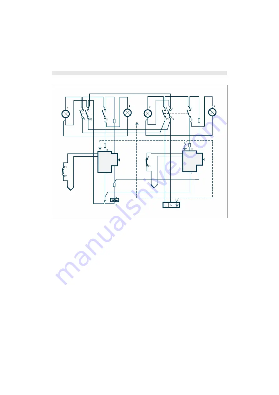
ELECTRIC DIAGRAM
1)
Terminal block
2)
Switch with coaxial thermostat -LH fryer
3)
Mains power indicator light -LH fryer
4)
Thermostat indicator light -LH fryer
5)
Gas solenoid valve with ignition contact - LH fryer
6)
Electronic ignition device
7)
Safety thermostat-LH fryer
8)
Thermocouple - LH fryer
9)
Switch with coaxial thermostat - RH fryer
10)
Mains power indicator light - RH fryer
11)
Thermostat indicator light -RH fryer
12)
Gas solenoid valve with ignition contact - RH fryer
13)
Safety thermostat - RH fryer
14)
Thermocouple - RH fryer
IDM-39603312600.tif
1
6
8
7
5
14
13
10
11
4
9
3
2
12


