background image

- 11 -

3378750_ut_FR 

FRANÇAIS

FR

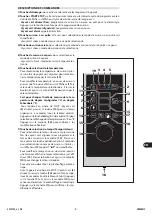
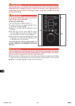
PRÉCHAUFFAGE AUTOMATIQUE

REAL

INJ

1

2

7

10

12

Importante

Important

Afi n d’obtenir un meilleur résultat de cuisson du 
produit, il est conseillé d’eff ectuer le préchauff age 
à four vide.

1) 

Presser la touche 

(2)

 pour activer l’appareil.

L’appareil eff ectue automatiquement une phase de 
préchauff age.
À la fi n du préchauff age, un signal sonore s’active. 
Enfourner et refermer la porte. La cuisson partira 
automatiquement.

Importante

Important

Le préchauff 

age est automatiquement exclu 

même lorsque la température à l’intérieur de la 
chambre de cuisson est déjà suffi

  sante  pour  le 

mode de cuisson sélectionné.

Exclusion temporaire :

 il est possible d’exclure cette 

fonction uniquement pour la cuisson en cours.

1) 

En phase de STOP (ou de pause cuisson, avec le 
voyant du touche 

(2)

 allumé fi xe), presser le bouton 

(2)

 pour un temps supérieur à une seconde.

Appuyer sur le bouton de réglage pour mémoriser la valeur et ensuite sur le bouton 

(2)

 pour 

lancer le démarrage retardé. 
Pour interrompre le compte à rebours et sortir de la fonction, appuyer sur le bouton 

(2)

 (la 

cuisson ne démarre pas). Si l’on souhaite faire partir la cuisson avant l’échéance du temps confi -
guré, appuyer sur le bouton 

(7)

 et agir sur le bouton de réglage 

(10)

 pour porter la valeur 

affi

  chée à l’écran 

(12)

 à « 

0

 »

18) Interrupteur principal: 

pour la commutation de l’alimentation électrique de l’appareil.

19) Icône brûleur :

 allumée, elle indique que le brûleur a été activé.

ALLUMAGE ET EXTINCTION DE L’APPAREIL

18

Procéder comme suit.

Allumage

1) 

Agir sur l’interrupteur sectionneur de l’appareil 
pour activer le branchement à la ligne électrique 
principale.

2) 

Ouvrir le robinet d’alimentation du gaz.

3) 

Ouvrir le robinet d’alimentation de l’eau.

4) 

Presser la touche 

(18)

 pour activer l’appareil.

Extinction

Importante

Important

Toujours éteindre l’appareil à la fi n de son utilisa-
tion.

1) 

Appuyer sur la touche 

(18)

 pour désactiver 

l’appareil.

2) 

Fermer le robinet d’alimentation du gaz.

3) 

Fermer le robinet d’alimentation de l’eau.

4) 

Agir sur l’interrupteur sectionneur de l’appareil 
pour désactiver le branchement à la ligne électrique 
principale.

Summary of Contents for BX101GW

Page 1: ...ructions avant d installer et d utiliser l appareil Léanse atentamente las instrucciones antes de instalar y utilizar el aparato Il mancato rispetto delle istruzioni fa decadere la garanzia del fabbricante In the event of failure to comply with the instructions the manufacturer s warranty shall cease to apply Die Missachtung der Anleitungen hat den Verfall der vom Hersteller gewährten Garantie zur...

Page 2: ...la Avvertenza L allacciamento deve essere effettuato da perso nale autorizzato e qualificato nel rispetto delle leggi vigenti in materia e con l utilizzo di materia le appropriato e prescritto Cautela Avvertenza Le regolazioni devono essere effettuate da per sonale autorizzato e qualificato nel rispetto delle leggi vigenti in materia FUNZIONAMENTO Importante Rischio di incendio Non inserire alimen...

Page 3: ...nciare e completare un programma LH2O WASHING LAVAGGIO LH2O prima di aprire lo sportello Importante Quando si usano prodotti detergenti per la pulizia e l igienizzazione dell apparecchiatura indossare i dispositivi di protezione individuali guanti ma scherine occhiali ecc come richiesto dalle leggi vigenti in materia di sicurezza e salute MANUTENZIONE Importante Tutti gli interventi di manutenzion...

Page 4: ......

Page 5: ...RUZIONI E AVVERTENZE DI SICUREZZA PER L EQUIPAGGIAMENTO ELETTRICO 6 USO E FUNZIONAMENTO 6 ISTRUZIONI E AVVERTENZE PER L USO 6 DESCRIZIONE COMANDI 7 ACCENSIONE E SPEGNIMENTO APPARECCHIATURA 11 PRERISCALDAMENTO AUTOMATICO 11 AVVIAMENTO E ARRESTO CICLO DI COTTURA 12 LAVAGGIO APPARECCHIATURA 13 INATTIVITÀ PROLUNGATA DELL APPARECCHIATURA 15 MANUTENZIONI 15 ISTRUZIONI E AVVERTENZE PER LA MANUTENZIONE 15...

Page 6: ...con sultarlo Il Fabbricante si riserva il diritto di apportare modifiche senza l obbligo di fornire preventivamen te alcuna comunicazione Per evidenziare alcune parti di testo di rilevante importanza o per indicare alcune specifiche impor tanti sono stati adottati alcuni simboli il cui significato viene di seguito descritto Cautela Avvertenza Indica che è necessario adottare comportamenti adeguati...

Page 7: ...ersioni vedi figura Organi principali A Pannello vano componenti elettrici B Pannello comandi C Porta del forno D Camera di cottura E Tubo aspirazione aria e scarico vapore F Tubo scarico vapore G Tubo scarico fumi D A B C F D A B C D A B C D A B C E G F E G F E G F E G MODELLO BX 61GW 61GWR MODELLO BX 101GW 101GWR MODELLO BX 82GW MODELLO BX 122GW INFORMAZIONI TECNICHE MODALITÀ DI RICHIESTA ASSIST...

Page 8: ... di gas di alimentazione ACCESSORI A RICHIESTA A richiesta l apparecchiatura può essere corredata dei seguenti accessori vedi catalogo ge nerale DATI TECNICI Descrizione BX 61GW 61GWR BX 101GW 101GWR BX82GW BX122GW Dimensioni forno 920x776x 630 100 mm 920x776x 875 100 mm 1178x965x 1315 150 mm 1178x965x 1315 150 mm Alimentazione elettrica 230V 1N 50 Hz 230V 1N 50 Hz 230V 1N 50 Hz 230V 1N 50 Hz 230V...

Page 9: ... per usi impropri può recare rischi per la sicurezza e la salute delle persone danni ai beni posti nelle vicinanze e danni economici Tutti gli interventi di manutenzione che richiedono una precisa competenza tecnica o partico lari capacità devono essere eseguiti esclusivamente da personale qualificato con esperienza riconosciuta e acquisita nel settore specifico di intervento Pulire accuratamente ...

Page 10: ... incendio I prodotti e i materiali utilizzati durante l attività produttiva e le fasi di manutenzione non devono contenere agenti contaminanti e corrosivi acidi sostanze chimiche sali ecc e non devono poter penetrare e o venire in contatto con i componenti elettrici Durantelefasiditrasportoedimmagazzinamentolatemperaturadell ambientedeveesse re compresa fra 25 C e 55 C L equipaggiamento elettrico ...

Page 11: ...volta per visualizzare sul display 11 il valore della temperatura impostata Premere il pulsante e agire sulla manopola 10 per variare il valore impostato Serve per cambiare l unità di misura della tem peratura da gradi Centigradi C a gradi Fah renheit F Con l apparecchiatura in fase di STOP spia verde 2 accesa premere il pulsante 14 per un tempo superiore a 3 secondi l intero pannello si spegne Te...

Page 12: ...o Serve per impostare la temperatura di cottura inter na del prodotto rilevata dalla sonda al cuore opzio nale o sottovuoto opzionale premere una volta la spia verde lampeggia per impostare la temperatura mediante la manopola 10 REAL INJ 1 2 3 4 5 6 7 8 9 10 11 12 13 14 15 16 17 18 19 Serve per modificare la temperatura in fase di cottura interna del prodotto premere una volta per visualizzare il ...

Page 13: ...ato chiuso 3 Fase 3 Convezione 125 C Sfiato aperto 1 P02 Programma di rigenerazione in piatto per carni di piccolo spessore e pe sce di grande spessore Preriscaldamento automatico 150 C Fase 1 Misto 130 C Umidità 10 3 Fase 2 Convezione 135 C Sfiato chiuso 3 Fase 3 Convezione 140 C Sfiato aperto 1 P03 Programma di rigenerazione in piatto per carni e pesce in generale au mentare il tempo in fase 2 p...

Page 14: ...3 la scritta P01 2 volte per visualizzare sul display 13 la scritta P02 3 volte per visualizzare sul display 13 la scritta P03 4 volte per visualizzare sul display 13 la scritta P04 5 volte per visualizzare sul display 13 la scritta dEC 6 volte per visualizzare sul display 13 la scritta SA 7 volte per visualizzare sul display 13 la scritta tcl 8 volte per visualizzare sul display 13 la scritta SPl...

Page 15: ...nel modo indicato Accensione 1 Agire sull interruttore sezionatore dell apparecchia tura per attivare l allacciamento alla linea elettrica principale 2 Aprire il rubinetto alimentazione gas 3 Aprire il rubinetto alimentazione acqua 4 Premere il pulsante 18 per attivare l apparecchia tura Spegnimento Importante Spegnere sempre l apparecchiatura a fine utilizzo 1 Premere il pulsante 18 per disattiva...

Page 16: ...ello per interrompere il ciclo di cottura in qualsiasi mo mento Per questa operazione procedere nel modo indicato Avviamento 1 Accendere l apparecchiatura vedi pag 11 2 Premere uno dei pulsanti 3 4 5 per impostare la modalità di cottura 3 Premere il pulsante 6 e agire sulla manopola 10 per impostare la temperatura di cottura 4 Premere il pulsante 7 e agire sulla manopola 10 per impostare il tempo ...

Page 17: ...Descrizione P01 2 22 Lavaggio consigliato per eliminare residui di difficilissima asportazione ad esem pio dopo la cottura a convezione di carni ad elevato contenuto di grassi come polli arrosti ecc P02 1 35 Lavaggio consigliato per eliminare residui di difficile asportazione ad esempio dopo la cottura a convezione di carne e o pesce P03 1 10 Lavaggio consigliato per eliminare residui di facile as...

Page 18: ... circa 5 minuti dall inizio del lavaggio e si accende la luce in camera di cottura immettere il detergente 4 Aprire la porta e spruzzare il detergente per uso ali mentare su tutte le pareti della camera di cottura sullo scambiatore e sulla ventola Per eseguire questa operazione è consigliabile l utilizzo dell accessorio nebulizzatore e del de tergente fornito dal fabbricante Cautela Avvertenza Qua...

Page 19: ...a Avvertenza Almeno una volta ogni 6 mesi oppure in caso di cotture frequenti di carne o cibi grassi ogni 2 mesi eseguire la pulizia dello sfiato vedi pag 19 Annualmente fare eseguire da operatori esperti e autorizzati le seguenti operazioni Controllo pressione gas e tenuta impianto Verifica efficienza canna fumaria prese d aria ed eventuale pulizia Verifica tenuta delle guarnizioni dello scambiat...

Page 20: ...ati Cautela Avvertenza Durante l utilizzo di detergenti è obbligatorio utilizzare guanti in gomma maschera anti inalazione ed occhiali di protezione secondo le norme di sicurezza vigenti 1 Nel maneggiare i prodotti detergenti usare sempre la massima cautela 2 Spruzzare solo piccole quantità di detergente 3 Non spruzzare detergente su superfici troppo calde 4 Non spruzzare detergente su persone o a...

Page 21: ...e il pannello deflettore D 5 Inumidire con acqua tutte le pareti della camera di cottura lo scambiatore e la ventola Per eseguire questa operazione è consigliabile l u tilizzo dell accessorio lancia di lavaggio 6 Spruzzare e lasciare agire per 10 15 min il deter gente per uso alimentare su tutte le pareti della camera di cottura sullo scambiatore e sulla ventola Per eseguire questa operazione è co...

Page 22: ... B posti sotto l apparecchiatura e pulirli con uno sgrassante idoneo Si consiglia il lavaggio in lavastoviglie PULIZIA SFIATO Per questa operazione procedere nel modo indicato 1 Far funzionare il forno a vapore a 100 C per mezzora 2 Spegnere il forno e staccare l interruttore di alimentazione 3 Spruzzare il detergente dall estremità del tubo di sfiato A e lasciare agire per almeno 15 minuti 4 Risc...

Page 23: ...mportante Per qualsiasi esigenza rivolgersi alle agenzie o alla sede centrale Angelo Po i cui riferimenti sono riportati nella sezione contatti del sito internet http www angelopo com Inconveniente Causa Rimedio L apparecchiatura non si ac cende Fusibile intervenuto Sostituire il fusibile vedi istruzioni per l installatore Intervento di un dispositivo di sicurez za o salvaguardia termostato di sic...

Page 24: ...llegata non correttamente Avvertire il servizio assistenza Le funzioni del forno sono di sabilitate e quindi non è possi bile eseguire cicli di cottura E02 La sonda al cuore non è inseri ta nel cibo oppure in avaria Verificare la posizione della sonda al cuore o avvertire il servizio assi stenza in caso di avaria Non è possibile effettuare cicli di cottura con sonda al cuore E03 La sonda scarico v...

Page 25: ...tura Se il problema persiste contat tare il servizio assistenza E22 Il ciclo di lavaggio si è interrot to per mancanza di sanificante Controllare la posizione del tubo e il livello di sanificante nel reci piente se necessario effettuare il rabbocco e riavviare il ciclo di lavaggio Se non è possibile ter minare il lavaggio procedere al risciacquo d emergenza o risciac quare manualmente la camera di...

Page 26: ...t legal requirements using appropriate and speci fied materials Important Adjustments must be carried out by authorised qualified staff in accordance with the relevant le gal requirements OPERATION Important Fire risk Do not place foods containing highly fl ammable ingredients alcoholbased foods in the oven These substances may burst into flames and therefore constitute a fire and explosion hazard...

Page 27: ...ASHING program before opening the door Important When cleaning and sanitising the appliance with detergents wear personal protection equipment gloves masks goggles etc as required by the relevant health and safety legislation SERVICING Important TuAll maintenance work that requires precise technical expertise or particular skills or qualifi cations for legal reasons should be carried out by suitab...

Page 28: ......

Page 29: ... SAFETY WARNINGS AND INSTRUCTIONS CONCERNING ELECTRICAL EQUIPMENT 6 USE AND OPERATION 6 INSTRUCTIONS AND WARNINGS FOR USE 6 DESCRIPTION OF CONTROLS 7 SWITCHING THE APPLIANCE ON AND OFF 11 AUTOMATIC PREHEATING 11 STARTING AND STOPPING THE COOKING CYCLE 12 WASHING APPLIANCE 13 LENGTHY DOWNTIMES OF APPLIANCE 15 SERVICING 15 INSTRUCTIONS AND WARNINGS FOR SERVICING 15 INSTRUCTIONS AND WARNINGS FOR CLEA...

Page 30: ...nsultation The manufacturer reserves the right to make changes without any obligation to provide any prior notice A number of symbols have been used to highlight particularly important parts of the text or important specifications Their meaning is as defined below Caution Warning Indicates that suitable procedures must be adopted to avoid putting people s health and safety at risk or causing econo...

Page 31: ...Parts A Electrical component compartment panel B Control board C Oven door D Cooking chamber E Air intake and steam exhaust pipe F Steam exhaust pipe G Flue pipe D A B C F D A B C D A B C D A B C E G F E G F E G F E G MODEL BX 61GW 61GWR MODEL BX 101GW 101GWR MODEL BX 82GW MODEL BX 122GW TECHNICAL INFORMATION GENERAL DESCRIPTION OF APPLIANCE PROCEDURE FOR REQUESTING SERVICE For all requirements co...

Page 32: ...ance can be equipped with the following accessories on request see general cata logue TECHNICAL DATA Description BX 61GW 61GWR BX 101GW 101GWR BX 82GW BX 122GW Oven dimensions 920x776x 630 100 mm 920x776x 875 100 mm 1178x965x 1315 150 mm 1178x965x 1315 150 mm Electricity supply 230V 1N 50 Hz 230 1N 50 Hz 230 1N 50 Hz 230 1N 50 Hz 230V 1N 60 Hz 230V 1N 60 Hz 230V 1N 60 Hz 230V 1N 60 Hz Selector swi...

Page 33: ...turer Improper use of the equipment could result in risks to the health and safety of people damage to nearby goods and financial losses All maintenance work that requires precise technical expertise or particular skills or qualifica tions for legal reasons should be carried out by suitably trained and or qualified staff and in any case with recognised experienced gained in the specific field of i...

Page 34: ...sent a fire hazard The products and materials used during production and maintenance must not contain contaminants or corrosives acids chemicals salts etc and must not be able to penetrate and or come into contact with the electrical components During transport and storage the ambient temperature must be between 25 C and 55 C However the electrical equipment may be exposed to a temperature of up t...

Page 35: ...on and hold it down for longer than 3 seconds the whole panel powers down Press and hold the button 6 and turn the knob 10 to select temperature display in C or F Press the knob 10 to confirm the changes made 7 Time setting button Timer To set the cooking time press once the green light flashes to set the cooking time using the knob 10 Keep the button pressed for about 2 seconds to set an unlimite...

Page 36: ...ved This function disables use of the Time setting button Timer 10 Control knob For varying the values of the functions selected see buttons 6 7 8 9 Turn the knob clockwise to increase the value and anti clockwise to decrease it REAL INJ 1 2 3 4 5 6 7 8 9 10 11 12 13 14 15 16 17 18 19 Used to modify the cooking and washing programming parameters and the appliance s func tional parameters Also conf...

Page 37: ... 135 C vent closed 3 Stage 3 Convection 140 C vent open 1 P03 Food in dish regeneration program for meat and fish in general increase the time in stage 2 for pasta or stuffed items Automatic preheating 150 C Stage 1 Combined 130 C Humidity 10 2 Stage 2 Convection 140 C vent closed 5 Stage 3 Convection 140 C vent open 3 P04 Cooking program product core probe for lean roast pork Automatic preheating...

Page 38: ... show the message P02 3 times and the display 13 will show the message P03 4 times and the display 13 will show the message P04 5 times and the display 13 will show the message dEC 6 times and the display 13 will show the message SA 7 times and the display 13 will show the message tcl 8 times and the display 13 will show the message SPl 9 times and the display 12 will show the message CLd Quick co...

Page 39: ...ne second SWITCHING THE APPLIANCE ON AND OFF Proceed as follows Switching on 1 Operate the appliance s master switch to connect it to the electrical mains 2 Turn on the gas supply tap 3 Turn on the water supply tap 4 Press button 18 to switch on the appliance Switching off Important Always switch off the appliance after use 1 Press button 18 to switch off the appliance 2 Turn off the gas supply ta...

Page 40: ...ber goes out 1 Press button 2 or open the door to interrupt the cooking cycle at any moment To carry out this operation proceed as follows Starting 1 Switch on the appliance see pag 11 2 Press one of the buttons 3 4 5 to set the cooking mode 3 Press button 6 and turn the knob 10 to set the cooking temperature 4 Press button 7 and turn the knob 10 to set the cooking time or press button 9 and turn ...

Page 41: ...NJ 2 11 12 13 14 16 Programs Total time Description P01 2 22 Cleaning program recommended for dealing with very stubborn residues e g af ter convection cooking of meat with high fat content such as chickens roasts etc P02 1 35 Cleaning program recommended for dealing with stubborn residues e g after convection cooking of meat and or fish P03 1 10 Cleaning program recommended for dealing with easil...

Page 42: ...in after wash ing starts and the light inside the cooking cham ber on place the detergent 4 Open the door and spray the food approved deter gent onto all the walls of the cooking chamber the heat exchanger and the fan Use of the cleaner spray accessory and the de tergent provided by the manufacturer is recom mended for this procedure REAL INJ 2 14 16 Caution Warning When cleaning and sanitising th...

Page 43: ... 6 months or if meat or greasy foods are cooked frequently every 2 months clean the vent see page 19 Every year have skilled authorised personnel carry out the following operations A check on the gas pressure and system tightness A check on the efficiency of the flues and air intakes cleaning them if necessary Check the tightness of the gaskets of the heat exchanger and replace them if necessary C...

Page 44: ...portant Caution Warning When using detergents rubber gloves protective mask and safety goggles must be worn in accordance with the relevant safety regulations 1 Always take the greatest care when handling detergents 2 Spray only small amounts of detergent 3 Never spray detergent onto excessively hot surfaces 4 Never spray detergent at people or animals 5 Follow the instructions provided on the det...

Page 45: ...l parts of the cooking chamber walls heat exchanger fan with warm drinking quality water The washing spray gun should be used to wet the inside of the cooking chamber 6 Spray the food approved cleaner onto all internal parts of the cooking chamber walls heat exchang er fan and leave it to act for 10 15 min The cleaning spray should be used to spray the cleaner onto the inside of the cooking chambe...

Page 46: ...rical mains 3 Remove air filters A and B located under the appliance and clean them with asuitable de greaser We recommend washing them in the dishwasher A B VENT CLEANING To carry out this operation proceed as follows 1 Run the steam oven at 100 C for half an hour 2 Switch off the oven and disconnect the power supply switch 3 Spray cleaning solution from the end of the vent hose A and let it sit ...

Page 47: ...ector of operation Important For all requirements contact the agents or the headquarters of Angelo Po which can be found in the contacts section of the website http www angelopo com Fault Cause Remedy The appliance does not switch on Fuse blown Replace the fuse see installation manual Safety or protection device safety thermostat or overload cutout tripped Press device reset button Electronic circ...

Page 48: ... are disa bled so no cooking cycles can be carried out E02 The product core probe is not inserted in the food or has failed Check the position of the prod uct core probe or inform the af ter sales service if it is faulty Cooking cycles with product core probe cannot be carried out E03 The steam discharge probe has failed Inform the after sales service Convection and steam cook ing cycles can still...

Page 49: ...re is no sanitizing cleaner Check the pipe position and the level of sanitizing cleaner in the tank top up if necessary and re start the filling procedure If it is not possible to complete the cleaning operation perform an emergency rinse or rinse the cooking chamber by hand If the problem persists call the after sales service E24 E26 Automatic cleaning system failure Check that no residues of cle...

Page 50: ...se al personal autori zado y experto que deberá respetar las leyes vi gentes en materia y utilizar siempre materiales adecuados y previstos por el constructor Precaución advertencia Lasregulacionesdebenserejecutadasporpersonal autorizado y cualificado en conformidad con lo dis puesto por las leyes vigentes en esta materia FUNCIONAMIENTO Importante Riesgo de incendio No coloque alimentos que conten...

Page 51: ... termine un programa de LAVADO LH2O antes de abrir la puerta Importante Al aplicar productos detergentes para la limpieza e higienización del aparato deberán utilizarse dis positivos de protección individual guantes mas carillas gafas etc en conformidad con lo dis puesto por las leyes vigentes sobre seguridad y salud MANTENIMIENTO Importante Todas las operaciones de mantenimiento que re quieran un...

Page 52: ......

Page 53: ... EL EQUIPAMIENTO ELÉCTRICO 6 USO Y FUNCIONAMIENTO 6 INSTRUCCIONES Y ADVERTENCIAS PARA EL USO 6 DESCRIPCIÓN DE LOS MANDOS 7 ENCENDIDO Y APAGADO DEL APARATO 11 PRECALENTAMIENTO AUTOMÁTICO 11 PUESTA EN MARCHA Y DETENCIÓN DEL CICLO DE COCCIÓN 12 LAVADO APARATO 13 PERÍODO PROLONGADO DE INACTIVIDAD DEL EQUIPO 15 MANTENIMIENTO 15 INSTRUCCIONES Y ADVERTENCIAS PARA EL MANTENIMIENTO 15 INSTRUCCIONES Y ADVER...

Page 54: ...de aportar modificaciones al equipo sin la obligación de comunicarlo previamente Para destacar determinadas partes relevantes del texto o para indicar algunas especificaciones im portantes se han empleado algunos símbolos cuyo significado se ilustrará a continuación Precaución advertencia Indica que es necesario adoptar comportamientos adecuados a fin de no crear situacio nes de riesgo para la sal...

Page 55: ...so véase figura Órganos principales A Panel armario componentes eléctricos B Panel de mandos C Puerta del horno D Cámara de cocción E Tubo de aspiración aire y descarga vapor F Tubo salida del vapor G Tubo de descarga humos D A B C F D A B C D A B C D A B C E G F E G F E G F E G MODELO BX 61GW 61GWR MODELO BX 101GW 101GWR MODELO BX 82GW MODELO BX 122GW INFORMACIONES DE CARÁCTER TÉCNICO MODALIDAD P...

Page 56: ...ación ACCESORIOS BAJO PEDIDO Bajo pedido el equipo puede ser suministrado con los accesorios que a continuación se indican vea el catálogo general DATOS TÉCNICOS Descripción BX 61GW 61GWR BX 101GW 101GWR BX 82GW BX 122GW Dimensiones horno 920x776x 630 100 mm 920x776x 875 100 mm 1178x965x 1315 150 mm 1178x965x 1315 150 mm Alimentación eléctrica 230V 1N 50 Hz 230V 1N 50 Hz 230V 1N 50 Hz 230V 1N 50 H...

Page 57: ...y la salud de las personas daños a los bienes situados en los alrededores y daños económicos Todas las operaciones de mantenimiento que requieran una competencia técnica específica o especiales capacidades o cualificaciones previstas por la Ley tienen que ser realizadas exclusivamente por personal debidamente cualificado y o habilitado y de todas formas con experiencia reconocida y adquirida en el...

Page 58: ... durante la actividad productiva y las operaciones de mantenimiento no deben contener agentes contaminantes ni corrosivos ácidos sustan cias químicas sales etc ni ser capaces de penetrar o entrar en contacto con los compo nentes eléctricos Durante el transporte y almacenamiento la temperatura del ambiente debe estar com prendida entre 25 y 55 C No obstante los equipos eléctricos pueden ser expuest...

Page 59: ...ada Presionar el pulsador y operar con el mando 10 para modificar el valor programado Permite modificar la unidad de medida de la tem peratura de grados Centígrados C a grados Fahrenheit F Con el aparato en fase de STOP Piloto verde 2 en cendido apriete el pulsador 14 durante un tiem po superior a 3 segundos todo el panel se apaga Mantenga apretado el pulsador 6 y use el mando 10 para seleccionar ...

Page 60: ...cocción interna del producto medida por la sonda al corazón opcional o en vacío opcional presionar una vez el testigo verde centellea para programar la temperatura mediante el mando 10 REAL INJ 1 2 3 4 5 6 7 8 9 10 11 12 13 14 15 16 17 18 19 Permite modificar la temperatura en fase de cocción interna del producto presionar una vez para visualizar el valor de la temperatura en el monitor 12 Apriete...

Page 61: ...vección 130 C respiradero cerrado 3 Fase 3 Convección 125 C respiradero abierto 1 P02 Programa de regeneración en plato para carnes de poco espesor y pescado de gran espesor Precalentamiento automático 150 C Fase 1 Mixto 130 C Humedad 10 3 Fase 2 Convección 135 C respiradero cerrado 3 Fase 3 Convección 140 C respiradero abierto 1 P03 Programa de regeneración en plato para carnes y pescado en gener...

Page 62: ...do de STOP presionar el botón 16 una vez para visualizar en el display 13 el mensaje P01 2 veces para visualizar en el display 13 el mensaje P02 3 veces para visualizar en el display 13 el mensaje P03 4 veces para visualizar en el display 13 el mensaje P04 5 veces para visualizar en el display 13 el mensaje dEC 6 veces para visualizar en el display 13 el mensaje SA 7 veces para visualizar en el di...

Page 63: ...trucciones Encendido 1 Con el interruptor aislador del aparato activar la co nexión a la línea eléctrica principal 2 Abrir la llave de alimentación del gas 3 Abrir la llave de alimentación del agua 4 Pulsar el botón 18 para accionar el aparato Apagado Importante Apagar siempre el aparato cuando termine de usarlo 1 Pulsar el botón 18 para desactivar el aparato 2 Cerrar el grifo de alimentación del ...

Page 64: ...o abrir la puerta para interrumpir el ciclo de cocción en cualquier mo mento Puesta en marcha 1 Encender el aparato véase pág 10 2 Pulsarunodelospulsadores 3 4 5 paraprogramar el método de cocción deseado 3 Pulsar el pulsador 6 y regular el mando 10 para programar la temperatura de cocción 4 Pulsar el pulsador 7 y operar con el mando 10 para programar el tiempo de cocción o bien pre sionar el botó...

Page 65: ...as tiempo total Descripción P01 2 22 Lavado recomendado para eliminar residuos de muy difícil remoción por ejemplo después de cocciones de convección de carnes con elevado contenido de grasa tales como pollo asado etc P02 1 35 Lavado recomendado para eliminar residuos de difícil remoción por ejemplo de spués de cocciones de convección de carne y o pescado P03 1 10 Lavado recomendado para eliminar ...

Page 66: ... desde el inicio del lavado y la luz se enciende en la cámara de cocción introdu cir el detergente 4 Abrir la puerta y rociar el detergente para uso ali menticio sobre todas las paredes de la cámara de cocción sobre el intercambiador de calor y sobre el ventilador Para realizar esta operación se aconseja el uso del accesorio nebulizador y del detergente suminis trado por el fabricante REAL INJ 2 1...

Page 67: ...ie el respiradero al menos una vez cada 6 meses o en caso de cocciones frecuentes de carne o comidas grasas cada 2 meses véase la pág 19 Todos los años asigne a operadores expertos y autorizados la realización de las siguien tes operaciones Controlar presión gas y hermeticidad del sistema Control de la eficiencia de la chimenea de las tomas de aire y eventual limpieza Control del sellado de las ju...

Page 68: ...a Al aplicar los detergentes es obligatorio utilizar guantes en goma mascarilla contra inhalaciones y gafas de protección en conformidad con lo dispuesto por las normas vigentes sobre seguridad 1 Los productos detergentes deben manipularse siempre con máximo cuidado 2 Rociar sólo pequeñas cantidades de detergente 3 No rociar detergente sobre superficies demasiado calientes 4 No rociar detergente s...

Page 69: ... C 4 Destornillar los tornillos para abrir el panel deflector D 5 Humedecer con agua todas las partes de la cámara de cocción el cambiador de calor y el ventilador Para realizar esta operación se aconseja el uso del accesorio ducha de lavado 6 Vaporizar el detergente para uso alimenticio sobre las paredes de la cámara de cocción sobre el cam biador de calor y sobre el ventilador y déjelo actuar po...

Page 70: ... la alimentación eléctrica 3 Retire los filtros de aire A e B colocados debajo del equipo límpielos con undesengrasante adecuado Se recomienda lavar en lavavajillas A B LIMPIEZA DEL RESPIRADER Para efectuar esta operación aplicar las siguientes instrucciones 1 Haga funcionar el horno a vapor a 100 C durante media hora 2 Apague el horno y desconecte el interruptor de alimentación 3 Rocíe el deterge...

Page 71: ...co de intervención Importante Para cualquier necesidad diríjase a las agencias o a la sede central de Angelo Po cuyos referentes se indican en la sección de contactos del sitio web http www angelopo com Inconveniente Causa Remedio El aparato no se enciende Fusible activado Cambie el fusible véase Instrucciones para el instalador Activación de un dispositivo de seguridad o protección termostato de ...

Page 72: ...o de asistencia Lasfuncionesdelhornoestándesha bilitadasy portanto nopueden llevarseacabolosciclosdecocción E02 La sonda al corazón del producto no está colocada dentro de la comida o está rota Controlar la posición de la sonda al corazón del producto o ponerse en contacto con el servicio de asistencia en caso de avería No pueden llevarse a cabo ciclos de cocción con la sonda al corazón del produc...

Page 73: ...a sírvase contactar con el servicio de asistencia E22 The washing cycle has been interrupted because there is no sanitizing cleaner Controlar la posición del tubo y el nivel del sanificante en el reci piente en caso de ser necesario rellenar y reanudar el ciclo de lavado Si no es posible concluir el la vado efectuar el enjuague de emergencia o enjuagar manual mente la cámara de cocción En caso de ...

Page 74: ... dommages au produit de la part du fabricant Important Ne pas installer l appareil près de murs inflam mables Attention Le branchement doit être fait par du personnel autorisé et qualifié conformément aux lois en vi gueur à ce sujet en utilisant le matériel approprié et prescrit Attention Les réglages doivent être faits par du personnel autorisé et qualifié dans le respect des lois en vi gueur en ...

Page 75: ...t avec la peau ou les yeux Si le programme de lavage est arrêté avant la fin lancez et complétez un programme LH2O DE LAVAGE avant d ouvrir la porte Important Quand on utilise des produits détergents pour le nettoyage et l hygiénisation de l ap pareil porter les équipements de protection individuels gants masques lunettes etc conformément aux lois en vigueur en matière de sécurité et de santé ENTR...

Page 76: ......

Page 77: ...UIPEMENT ÉLECTRIQUE 6 UTILISATION ET FONCTIONNEMENT 6 INSTRUCTIONS ET AVERTISSEMENTS POUR L UTILISATION 6 DESCRIPTION DES COMMANDES 7 ALLUMAGE ET EXTINCTION DE L APPAREIL 11 PRÉCHAUFFAGE AUTOMATIQUE 11 MISE EN MARCHE ET ARRÊT DU CYCLE DE CUISSON 12 LAVAGE DE L APPAREIL 13 INUTILISATION PROLONGÉE DE L APPAREIL 15 ENTRETIEN 15 INSTRUCTIONS ET AVERTISSEMENTS POUR L ENTRETIEN 15 INSTRUCTIONS ET AVERTI...

Page 78: ...réserve le droit d apporter des modifications sans l obligation de fournir préalable ment une communication Pour mettre en évidence certaines parties de texte très importantes ou pour indiquer certaines caractéristiques des symboles ont été utilisés dont le sens est décrit ci après Attention Indique qu il faut adopter des comportements appropriés pour ne pas mettre en péril la santé et la sécurité...

Page 79: ...s composants électriques B Tableau de commandes C Porte du four D Chambre de cuisson E Tuyau d aspiration de l air et d évacuation de la vapeu F Tuyau d évacuation de la vapeur G Tuyau d évacuation des fumées D A B C F D A B C D A B C D A B C E G F E G F E G F E G MODÈLE BX 61GW 61GWR MODÈLE BX 101GW 101GWR MODÈLE BX 82GW MODÈLE BX 122GW INFORMATIONS TECHNIQUES DESCRIPTION GÉNÉRALE DE L APPAREIL D...

Page 80: ...EMANDE Sur demande l appareil peut être équipé des accessoires suivants voir le catalogue général DONNÉES TECHNIQUES Description BX 61GW 61GWR BX 101GW 101GWR BX82GW BX122GW Dimensions du four 920x776x 630 100 mm 920x776x 875 100 mm 1178x965x 1315 150 mm 1178x965x 1315 150 mm Alimentation élec trique 230V 1N 50 Hz 230 1N 50 Hz 230 1N 50 Hz 230 1N 50 Hz 230V 1N 60 Hz 230V 1N 60 Hz 230V 1N 60 Hz 230...

Page 81: ...voquer des risques pour la sécurité et la santé des personnes des dommages aux biens placés à proximité et des dommages économiques Toutes les interventions de maintenance qui nécessitent une compétence technique précise ou de particulières capacités ou qualifications prévues par la loi doivent être effectuées exclu sivement par un personnel dûment qualifié et ou habilité et possédant en tout cas ...

Page 82: ...ndant le travail et les opérations d entretien ne doivent pas contenir d agents contaminants et corrosifs acides substances chimiques sels etc et ne doivent pas pouvoir pénétrer dans les composants électriques et ou entrer en contact avec eux Au cours du transport et du stockage la température du milieu ambiant doit être com prise entre 25 C et 55 C L équipement électrique peut être exposé à une t...

Page 83: ...température sélectionnée Presser le bouton et agir sur la manette 10 pour changer la valeur introduite Sert pour changer l unité de mesure de la tem pérature de degrés Centigrades C en degrés Fahrenheit F Avec l appareil en phase de STOP Voyant vert 2 allumé presser la touche 14 pour un temps supérieur à 3 secondes tout le tableau s éteint Appuyersurlatouche 6 etagirsurlamanette 10 pour sélectionn...

Page 84: ...us vide Elle sert pour sélectionner la température de cuisson interne du produit relevée par la sonde en option presser une fois le voyant vert clignote pour sélec tionner la température par la manette 10 Il sert pour modifier la température de cuisson à l intérieur du produit presser une fois pour afficher la valeur de la température sur l afficheur 12 Presser le bouton et agir sur la manette 10 ...

Page 85: ...ir pulsé 125 C Event ouvert 1 P02 Programme de régénération dans l assiette pour les viandes de petite épaisseur et le poisson de grosse épaisseur Préchauffage automatique 150 C Phase 1 Mixte 130 C Humidité 10 3 Phase 2 À air pulsé 135 C Event fermé 3 Phase 3 À air pulsé 140 C Event ouvert 1 P03 Programme de régénération dans l assiette pour les viandes et le poisson en général augmenter le temps ...

Page 86: ...deux fois pour afficher P02 sur l afficheur 13 trois fois pour afficher P03 sur l afficheur 13 4 fois pour afficher P04 sur l afficheur 13 5 fois pour afficher deC sur l afficheur 13 6 fois pour afficher SA sur l afficheur 13 7 fois pour afficher tcl sur l afficheur 13 8 fois pour afficher SPl sur l afficheur 13 9 fois pour afficher CLd refroidissement rapide sur l afficheur 13 Avec la fonction re...

Page 87: ...our lancer le démarrage retardé Pour interrompre le compte à rebours et sortir de la fonction appuyer sur le bouton 2 la cuisson ne démarre pas Si l on souhaite faire partir la cuisson avant l échéance du temps confi guré appuyer sur le bouton 7 et agir sur le bouton de réglage 10 pour porter la valeur affichée à l écran 12 à 0 18 Interrupteur principal pour la commutation de l alimentation électr...

Page 88: ...ette opération procéder comme suit Mise en marche 1 Allumer l appareil voir page 10 2 Appuyer sur l une des touches 3 4 5 pour sélec tionner le mode de cuisson 3 Appuyer sur la touche 6 et agir sur la manette 10 pour sélectionner la température de cuisson 4 Appuyer sur la touche 7 et agir sur la manette 10 pour sélectionner le temps de cuisson ou appuyer sur la touche 9 et agir sur la manette 10 p...

Page 89: ... pour éliminer les salissures très tenaces par exemple après la cuisson à air pulsé de viandes avec un contenu élevé de graisses comme les poulets les rôtis etc P02 1 35 Nettoyage conseillé pour éliminer les salissures tenaces par exemple après la cuisson à air pulsé de viande et ou de poisson P03 1 10 Nettoyage conseillé pour enlever les résidus facilement éliminables par exem ple après cuissons ...

Page 90: ...e s active après 5 minutes environ du début du lavage et la lumière s allume dans la chambre de cuisson mettre le détergent 4 Ouvrir la porte et vaporiser le détergent pour usage alimentaire sur les parois de la chambre de cuisson sur l échangeur et sur le ventilateur Pour cette opération il est conseillé d utiliser l ac cessoire atomiseur et le détergent fourni par le fabricant Attention Quand on...

Page 91: ...s les deux mois en cas de cuissons fréquentes de viande ou d aliments gras effectuer le nettoyage du tuyau d évent voir à la page 18 Annuellement faire exécuter par des opérateurs experts et autorisés les opérations suivantes Contrôle de la pression du gaz et de l étanchéité de l installation Vérification du bon fonctionnement de la mitre des prises d air et si nécessaire nettoyage Vérification de...

Page 92: ...ts en caoutchouc un masque de protection respiratoire et des lunettes de protection conformément aux normes de sécurité en vigueur 1 Faire très attention pour la manipulation de produits détergents 2 Ne vaporiser que de petites quantités de détergent 3 Ne pas vaporiser le détergent sur des surfaces trop chaudes 4 Ne pas vaporiser le détergent sur des personnes ou des animaux 5 Suivre les indicatio...

Page 93: ...filtre C 4 Dévisser les vis pour ouvrir le panneau déflecteur D 5 Humecter avec de l eau les parois de la chambre de cuisson l échangeur et le ventilateur Pour effectuer cette opération il est conseillé d utiliser l accessoire douchette de nettoyage 6 Vaporiser et laisser agir pendant 10 15 min le dé tergent pour usage alimentaire sur les parois de la chambre de cuisson sur l échangeur et sur le v...

Page 94: ... filtres à air A et B placés sous l appareil et les nettoyer à l aide d unproduit dé graissant approprié Il est conseillé d effectuer le lavage au lave vaisselle A B NETTOYAGE DU TUYAU D ÉVENT Pour cette opération procéder comme suit 1 Faire fonctionner le four à vapeur à 100 C pendant une demi heure 2 Éteindre le four et débrancher l interrupteur d alimentation 3 Pulvériser le détergent par l ext...

Page 95: ...portante Important Pour toute exigence s adresser aux agences ou au siège centra Angelo Po dont les références sontreportéesdanslasectioncontactsdusiteinternethttp www angelopo com Inconvénient Cause Solution L appareil ne s allume pas Fusible sauté Remplacer le fusible voir instruc tions pour l installation Intervention d un dispositif de sécurité ou de sauvegarde ther mostat de sécurité ou relai...

Page 96: ...on est en avarie ou n est pas raccordée correctement Avertir le service assistance Les fonctions du four sont désactivées il n est donc pas possible d effectuer les cycles de cuisson E02 La sonde à coeur n est pas introduite dans l aliment ou est en avarie Vérifier la position de la sonde à coeur ou avertir le service assis tance en cas d avarie Il n est pas possible d effectuer les cycles de cuis...

Page 97: ... le ser vice assistance E22 Le cycle de nettoyage s est interrompu par manque de stérilisant Contrôler la position du tuyau et le niveau de stérilisant dans le récipient si nécessaire ajou ter du stérilisant et faire repar tir le cycle de nettoyage Si le lavage ne peut être terminé effectuer le rinçage d urgence ou rincer manuellement la chambre de cuisson Si nécessaire appeler le ser vice assista...

Page 98: ...r Nähe von Wänden aus ent flammbarem Material installieren Vorsicht Achtung Der Anschluss muss von autorisiertem Fachper sonal in Einklang mit den einschlägigen gesetzli chen Bestimmungen und unter Verwendung von geeignetem und vorschriftsmäßigem Material ausgeführt werden Vorsicht Achtung Die Einstellungen sind gemäß den einschlägigen geltenden Gesetzesbestimmungen vom autori sierten Fachmann dur...

Page 99: ...m Öffnen der Tür ein LH2O REINIGUNGSPROGRAMM starten und vollständig durchlaufen lassen Wichtig Beim Reinigen des Geräts mit Reinigungs und Desinfektionsmitteln die von den Sicherheits und Gesundheitsschutzbestimmungen vorgeschrie benen Körperschutzmittel tragen Schutzhand schuhe Atemschutzmaske Schutzbrille usw WARTUNG Wichtig Alle Wartungseingriffe die technisches Fach wissen oder spezielle Fähi...

Page 100: ......

Page 101: ...TUNGEN UND SICHERHEITSANWEISUN GEN FÜR DIE ELEKTRISCHE AUSRÜSTUNG 6 GEBRAUCH UND BETRIEB 6 ANWEISUNGEN UND WARNHINWEISE FÜR DIE BEDIENUNG 6 BESCHREIBUNG DER BEDIENELEMENTE 7 EIN UND AUSSCHALTEN DES GERÄTS 11 AUTOMATISCHES VORHEIZEN 11 STARTEN UND STOPPEN DES GARZYKLUS 12 WASCHEN DES GERÄTS 13 LÄNGERER STILLSTAND DES GERÄTS 15 WARTUNG 15 ANWEISUNGEN UND WARNHINWEISE FÜR DIE WARTUNG 15 ANWEISUNGEN U...

Page 102: ...uch für die gesamte Lebensdauer des Gerätes an einem bekannten und leicht zugänglichen Ort auf damit es immer griffbereit zur Verfügung steht wenn etwas nachgeschlagen werden muss Der Hersteller behält sich das Recht vor ohne jegliche Pflicht einer vorherigen Mitteilung Änderungen vorzunehmen UmbestimmteTextstellenvonbesondererBedeutunghervorzuhebenoderaufwichtigeSpezifika tionen hinzuweisen sind ...

Page 103: ...ktrischen Komponenten B Bedienfeld C Ofentür D Garraum E Luftansaug und Dampfablassleitung F Dampfablassrohre G Rauchabzugsleitung D A B C F D A B C D A B C D A B C E G F E G F E G F E G MODELLE BX 61G 61GWR MODELLE BX 101G 101GWR MODELLE BX 82GW MODELLE BX 122GW TECHNISCHE INFORMATIONEN ALLGEMEINE BESCHREIBUNG DES GERÄTS KUNDENDIENST ANFORDERN Bei Rückfragen wenden Sie sich bitte an die Handelsve...

Page 104: ...ge Gasart OPTIONALES ZUBEHÖR Auf Wunsch kann das Gerät mit folgenden Zubehörteilen ausgestattet werden siehe Haupt katalog TECHNISCHE DATEN Beschreibung BX 61GW 61GWR BX101GW 101GWR BX82GW BX122GW Abmessungen des Backofens 920x776x 630 100 mm 920x776x 875 100 mm 1178x965x 1315 150 mm 1178x965x 1315 150 mm Spannungsversor gung 230V 1N 50 Hz 230 1N 50 Hz 230 1N 50 Hz 230 1N 50 Hz 230V 1N 60 Hz 230V ...

Page 105: ...gesehenen Verwendungszwecke ein Die unsachgemäße Verwendung des Gerätes kann sowohl die Sicherheit als auch die Gesundheit der Personen gefährden Gegenstände die sich in seiner Nähe befinden beschädigen und wirtschaftliche Schäden verursachen Alle Wartungseingriffe die technisches Fachwissen oder spezielle Fähigkeiten oder eine ge setzlich vorgeschriebene Ausbildung erfordern dürfen ausschließlich...

Page 106: ...verwendeten Produkte und Materialien dürfen keine kontaminierenden und korrosiven Stoffe Säuren chemische Substanzen Salze usw enthalten und dürfen nicht mit den elektrischen Komponenten in Kontakt kommen und oder in sie eindringen Während des Transports und der Lagerung muss die Umgebungstemperatur zwischen 25 C und 55 C betragen Die elektrische Ausrüstung darf jedoch Temperaturen bis 70 C ausges...

Page 107: ...m Ändern des einge stellten Werts Taste 10 drücken und den Schalter betätigen Sie dient zum Ändern der Maßeinheit der Tem peratur von Grad Celsius C in Grad Fahrenheit F Mit Gerät in STOP Phase Grüne Kontrolllampe 2 eingeschaltet den taste 14 länger als 3 Sekunden drücken die gesamte Steuertafel wird ausgeschal tet Den taste 6 drücken und den Drehknopf 10 für die Auswahl der Temperaturanzeige in C...

Page 108: ...erntemperaturfühler oder den Fühler fürVaku umverpackungen Sie dient zum Einstellen der Kerntemperatur des Gar guts die vom Kerntemperaturfühler optional oder dem Fühler für Vakuumverpackungen optional gemessen wird Einmal drücken die grüne Kontroll leuchte blinkt um die Temperatur mit dem Schalter 10 einzustellen REAL INJ 1 2 3 4 5 6 7 8 9 10 11 12 13 14 15 16 17 18 19 Sie dient zum Ändern der Ke...

Page 109: ... 1 Kombi 110 C Feuchtigkeit 10 2 Phase 2 Heißluft 130 C Entlüftung zu 3 Phase 3 Heißluft 125 C Entlüftung auf 1 P02 Programm für Aufwärmen auf Teller für Fleisch geringer Stärke und Fisch großer Stärke Automatisches Vorheizen 150 C Phase 1 Kombi 130 C Feuchtigkeit 10 3 Phase 2 Heißluft 135 C Entlüftung zu 3 Phase 3 Heißluft 140 C Entlüftung auf 1 P03 Programm für Aufwärmen aufTel ler für Fleisch u...

Page 110: ... Im Zustand STOP die Taste 16 drücken Einmalig um auf dem Display 13 die Aufschrift P01 Zweimalig um auf dem Display 13 die Aufschrift P02 Dreimalig um auf dem Display 13 die Aufschrift P03 Viermalig um auf dem Display 13 die Aufschrift P04 5 mal um auf dem Display 13 die Aufschrift dEC 6 mal um auf dem Display 13 die Aufschrift SA 7 mal um auf dem Display 13 die Aufschrift tcl 8 mal um auf dem Di...

Page 111: ...pf betätigen um den Wert zu speichern und dann die Taste 2 drücken um den verzögerten Start zu aktivieren Um den Count down zu unterbrechen und die Funktion zu verlassen die Taste 2 drücken der Garvorgang startet nicht Wenn der Garvorgang gestartet werden soll bevor die eingestellte Zeit abgelaufen ist dieTaste 7 drücken und auf den Drehknopf 10 einwirken um den am Display angezeigtenWert 12 auf 0...

Page 112: ... Zeit punkt zu unterbrechen Für diesen Vorgang in der angegebenen Weise ver fahren Starten 1 Das Gerät einschalten siehe Seite 11 2 Mit einem der Tasten 3 4 5 die Beheizungsart einstellen 3 Taste 6 drücken und mit dem Schalter 10 die Gartemperatur einstellen 4 Die Taste 7 drücken und mit dem Schalter 10 die Gardauer einstellen oder die Taste 9 drücken und mit dem Schalter 10 die Temperatur für den...

Page 113: ...ng P01 2 22 Empfohlener Waschzyklus zum Beseitigen von sehr hartnäckigen Verschmut zungen zum Beispiel nach dem Braten mit Umluft von sehr fettigem Fleisch wie Hähnchen Braten usw P02 1 35 Empfohlener Waschzyklus zum Beseitigen von hartnäckigen Verschmutzungen zum Beispiel nach dem Braten von Fleisch und oder Fisch mit Umluft P03 1 10 Empfohlener Waschzyklus zum Beseitigen von leicht zu entfernend...

Page 114: ...des Waschvorgangs und das Licht im Garraum leuchtet auf das Reinigungsmittel geben 4 Die Tür öffnen und das lebensmitteltaugliche Reini gungsmittel auf alle Wände des Garraums auf den Wärmetauscher und auf den Ventilator sprühen Es wird empfohlen hierzu das Zubehör Sprüh pistole und das vom Hersteller gelieferte Reini gungsmittel zu verwenden REAL INJ 2 14 16 Vorsicht Achtung Beim Reinigen des Ger...

Page 115: ...nen siehe Seite 14 Vorsicht Achtung Mindestens ein Mal alle 6 Monate oder bei häufigen Garvorgängen von Fleisch oder fetten Speisen alle 2 Monate den Abzug reinigen siehe S 19 Jährlich von erfahrenem und autorisiertem Personal folgende Arbeiten ausführen lassen Kontrolle des Gasdrucks und der Dichtigkeit der Anlage Prüfung der Wirksamkeit und ggf Reinigung des Abzugsrohrs und der Luftöffnungen Prü...

Page 116: ...dschuhe Atemschutzmaske und Schutzbrille zu tragen sind 1 Reinigungsmittel stets mit größter Vorsicht handhaben 2 Nur geringe Mengen Reinigungsmittel aufsprühen 3 Das Reinigungsmittel nicht auf zu heiße Oberflächen sprühen 4 Das Reinigungsmittel nicht auf Personen oder Tiere sprühen 5 Die Anweisungen auf der Verpackung und im Sicherheitsdatenblatt des Reinigungsmittels be folgen 6 Verwenden Sie zu...

Page 117: ...ände des Garraums den Wärmetauscher und das Lüfterrad mit Wasser befeuchten Es wird empfohlen hierzu das Zubehör Schlauch brause zu verwenden 6 Das lebensmitteltaugliche Reinigungsmittel auf alle Wände des Garraums auf den Wärmetauscher und das Lüfterrad sprühen und rund 10 15 Minuten einwirken lassen Es wird empfohlen hierzu das Zubehör Sprühpistole zu verwenden A B 7 Die Oberflächen des Garraums...

Page 118: ...ch unter dem Gerät befinden und mit einem geeigne ten Entfettungsmittel reinigen Es wird eine Reinigung in der Spülmaschine empfohlen A B REINIGUNG DES ABZUGS Für diesen Vorgang in der angegebenen Weise verfahren 1 Ofen etwa eine halbe Stunde mit Dampf bei 100 C funktionieren lassen 2 Ofen ausschalten und den Versorgungsschalter ausschalten 3 Reinigungsmittel vom Ende des Abzugsrohrs A sprühen und...

Page 119: ...nden Sie sich bitte an die Handelsvertretungen oder den Hauptsitz des Unternehmens Angelo Po die entsprechenden Kontaktdaten sind auf der Webseite http www angelopo com unter Kontakt zu finden Störung Ursache Lösung Das Gerät schaltet sich nicht ein Sicherung ausgelöst Die Sicherung ersetzen siehe installationshandbuch Eine Sicherheitseinrichtung oder Schutzfunktion wurde ausgelöst Sicherheitsther...

Page 120: ...r Fühler im Garraum ist de fekt oder nicht richtig ange schlossen Den Kundendienst verständigen Da die Funktionen des Backofens gesperrt sind können keine Gar zyklen ausgeführt werden E02 Der Kerntemperaturfühler wurde nicht in die Speise ge steckt oder ist defekt Die Position des Kerntemperatur fühlers kontrollieren und im Falle eines Defekts den Kundendienst verständigen Es können keine Garzykle...

Page 121: ...sst den Kundendienst verständigen E22 Der Waschzyklus wurde un terbrochen weil Desinfekti onsmittel fehlt Die Position des Schlauchs und den Reinigungsmittelstand im Be hälter kontrollieren nötigenfalls nachfüllen und den Waschzyklus wieder starten Wenn die Spülung nicht been det werden kann ist eine Not spülung auszuführen oder der Garraum von Hand zu spülen Wenn sich das Problem nicht be heben l...

Page 122: ......

Page 123: ...rden Lire attentivement les instructions avant d installer et d utiliser l appareil Léanse atentamente las instrucciones antes de instalar y utilizar el aparato Il mancato rispetto delle istruzioni fa decadere la garanzia del fabbricante In the event of failure to comply with the instructions the manufacturer s warranty shall cease to apply Die Missachtung der Anleitungen hat den Verfall der vom H...

Page 124: ......

Page 125: ...AGGIAMENTO ELETTRICO 4 MANUTENZIONE 4 ISTRUZIONI E AVVERTENZE PER LA MANUTENZIONE 4 GUASTI 5 RICERCA GUASTI 5 TABELLA SEGNALAZIONE ALLARMI 5 PULIZIA SFIATO 5 MOVIMENTAZIONE E INSTALLAZIONE 6 ISTRUZIONI E AVVERTENZE PER LA MOVIMENTAZIONE E INSTALLAZIONE 6 IMBALLO E DISIMBALLO 6 TRASPORTO 6 MOVIMENTAZIONE E SOLLEVAMENTO 6 INSTALLAZIONE APPARECCHIATURA 7 VENTILAZIONE LOCALE 7 LIVELLAMENTO 7 ALLACCIAM...

Page 126: ...LO FUMI DI COMBUSTIONE 13 REGOLAZIONE PRESSIONE ACQUA 14 SOSTITUZIONE PARTI 14 ISTRUZIONI E AVVERTENZE PER LA SOSTITUZIONE PARTI 14 SOSTITUZIONE FUSIBILE 15 SOSTITUZIONE UGELLO BRUCIATORE 15 SOSTITUZIONE LAMPADA 16 SOSTITUZIONE CANDELETTA 16 DISMISSIONE DEMOLIZIONE E SMALTIMENTO APPARECCHIATURA 16 ALLEGATI ANNEXES I XXIII IT ...

Page 127: ...omento in cui è necessario con sultarlo Il Fabbricante si riserva il diritto di apportare modifiche senza l obbligo di fornire preventivamen te alcuna comunicazione Per evidenziare alcune parti di testo di rilevante importanza o per indicare alcune specifiche impor tanti sono stati adottati alcuni simboli il cui significato viene di seguito descritto Cautela Avvertenza Indica che è necessario adot...

Page 128: ...re DISPOSITIVI DI SICUREZZA Vedi paragrafo Dispositivi di sicurezza del manuale Istruzioni per l utilizzatore DOTAZIONE ACCESSORI Vedi paragrafo Dotazione accessori del manuale Istruzioni per l utilizzatore ACCESSORI A RICHIESTA Vedi paragrafo Accessori a richiesta del manuale Istruzioni per l utilizzatore SICUREZZA ISTRUZIONI E AVVERTENZE PER LA SICUREZZA Vedi paragrafo ISTRUZIONI E AVVERTENZE PE...

Page 129: ...no 15 minuti 4 Risciacquare il tubo spruzzando acqua all interno del tubo dall estremità aperta sul cielo del forno eseguire l operazione con il fianco del forno chiu so 5 Estrarre dall interno del forno il telaio portateglie B e pulirlo accuratamente 6 Svitare le viti per aprire il pannello deflettore C 7 Svitare le viti D per smontare la protezione E 8 Spruzzare il detergente all interno del tub...

Page 130: ...rtenza Eseguire la movimentazione e l installazione nel rispetto delle informazioni fornite dal Fabbricante e riportate direttamente sull imballo sull apparecchiatura e nelle istruzioni per l uso Tutte le operazioni di movimentazione e di installazione dovranno essere eseguite nel ri spetto della legislazione vigente in materia di salute e sicurezza sul lavoro TRASPORTO MOVIMENTAZIONE E SOLLEVAMEN...

Page 131: ...gli allacciamenti di alimentazione ventila zione aspirazione e di scarico dei residui di produzione deve essere adeguatamente illuminata ed avere tutti i requisiti igienici e sanitari rispondenti alle leggi vigenti per evitare che gli alimenti vengano contaminati Se necessario individuare l esatta posizione di ogni singola apparecchiatura o sottoinsieme trac ciando le coordinate per posizionarli c...

Page 132: ...IEC 898 2 Svitare le viti e smontare il pannello laterale A 3 Collegare l interruttore automatico sezionatore B alla morsettiera C dell apparecchiatura e alla rete elettrica di alimentazione secondo le indicazioni riportate nello schema elettrico in fondo al manua le e utilizzando un cavo con le seguenti caratteri stiche Peso del tipo H05RN F designazione 245 IEC 57 Temperatura di utilizzo 70 C B ...

Page 133: ...ier raccomandato 0 5 Contenuto di sali e ioni metallici Richiesti Cloro Cloruri Solfati 0 1 mg l 10 mg l 30 mg l Raccomandati Ferro Manganese Rame 0 1 mg l 0 05 mg l 0 05 mg l Il valore si riferisce alla quantità di acqua necessaria alla produzione di vapore all interno della ca mera di cottura Valori differenti da questi parametri possono causare corrosioni se combinati con un uso e ambiente sbag...

Page 134: ... igienicità e integrità dell acciaio inossidabi le necessarie per la protezione dalla corrosione è necessario lavare quotidianamente la camera di cottura vedi pagagrafo Puzia camera di cottura del manuale istruzioni dell u tilizzatore con prodotti detergenti idonei e asciugarla completamente prima dell utilizzo Cautela Avvertenza Eseguire la manutenzione del sistema di trattamento dell acqua se in...

Page 135: ... i detriti depo sitati B Ø17 ALLACCIAMENTO SCARICO GAS COMBUSTI Cautela Avvertenza Effettuare l allacciamento nel rispetto delle leggi vigenti in materia utilizzando il materiale appropriato e prescritto Cautela Avvertenza La temperatura massima dei gas combusti all usci ta è di circa 400 C Allacciamento sotto cappa ad aspirazione forzata Posizionare l apparecchiatura sotto la cappa C come indicat...

Page 136: ... P DE II2E3B P NL RO II2L3B P A C B COLLAUDO APPARECCHIATURA Cautela Avvertenza Prima della messa in servizio deve essere eseguito il collaudo dell impianto al fine di va lutare le condizioni operative di ogni singolo componente ed individuare le eventuali ano malie In questa fase è importante verificare che tutte le condizioni di sicurezza e di igiene siano rigorosamente rispettate 1 Aprire i rub...

Page 137: ...umi dell ap parecchiatura 3 Accendere l apparecchiatura vedi vedi paragrafo Accensione e spegnimento del manuale istruzioni dell utilizzatore 4 Attivare la procedura di Misurazione CO CO2 5 Verificare i valori delle emissioni di CO e CO2 prima alla potenza minima a freddo poi alla potenza massima e poi di nuovo alla potenza minima a caldo 6 Verificare che i valori ottenuti siano conformi con i req...

Page 138: ...are se sia necessario informare adeguatamente il personale che ope ra e quello nelle vicinanze In particolare chiudere il rubinetto alimentazione acqua disat tivare l alimentazione elettrica tramite l interruttore sezionatore dell apparecchiatura ed impedire l accesso a tutti i dispositivi che potrebbero se attivati provocare condizioni di pericolo inatteso causando danni alla sicurezza e alla sal...

Page 139: ... ad operazione ultimata SOSTITUZIONE UGELLO BRUCIATORE Per questa operazione procedere nel modo indicato 1 Svitare le viti per smontare il pannello laterale A 2 Scollegare il tubo alimentazione gas B 3 Estrarre l iniettore C e sostituirlo con quello adatto al tipo di gas utilizzato vedi tabella in fondo al manuale Cautela Avvertenza Prestare attenzione al corretto posizionamento dell iniettore C v...

Page 140: ...vvedere allo smaltimento differenziato nel rispetto delle leggi vigenti in materia Cautela Avvertenza Non disperdere nell ambiente prodotti non biodegradabili oli lubrificanti e componenti non ferrosi gomma PVC resine ecc Effettuare il loro smaltimento nel rispetto delle leg gi vigenti in materia A B A B C D D E SOSTITUZIONE LAMPADA Per questa operazione procedere nel modo indicato 1 Svitare le vi...

Page 141: ...NS CONCERNING ELECTRICAL EQUIPMENT 4 SERVICING 4 INSTRUCTIONS AND WARNINGS FOR SERVICING 4 FAULT 5 TROUBLESHOOTING 5 TABLE OF ALARM INDICATIONS 5 VENT CLEANING 5 HANDLING AND LIFTING 6 HANDLING AND INSTALLATION 6 INSTRUCTIONS AND WARNINGS FOR HANDLING AND INSTALLATION 6 PACKAGING AND UNPACKING 6 TRANSPORT 6 INSTALLATION OF THE APPLIANCE 7 ROOM VENTILATION 7 LEVELLING 7 ELECTRICAL CONNECTION 8 GAS ...

Page 142: ...ING THE COMBUSTION EXHAUST GASES 13 ADJUSTING THE WATER PRESSURE 14 REPLACING PARTS 14 INSTRUCTIONS AND WARNINGS FOR REPLACING PARTS 14 REPLACING THE FUSE 15 REPLACEMENT OF THE BURNER NOZZLE 15 CHANGING THE IGNITION PLUG 16 APPLIANCE DECOMMISSIONING DEMOLITION AND DISPOSAL 16 CHANGING THE LAMP 16 ALLEGATI ANNEXES I XXIII ...

Page 143: ...will always be available when required for consultation The manufacturer reserves the right to make changes without any obligation to provide any prior notice A number of symbols have been used to highlight particularly important parts of the text or important specifications Their meaning is as defined below Caution Warning Indicates that suitable procedures must be adopted to avoid putting people...

Page 144: ...he user instructions manual SAFETY DEVICES See point Safety devices of the user instructions manual STANDARD ACCESSORIES See point Standard accessories of the user instructions manual OPTIONAL ACCESSORIES See point Optional accessories of the user instructions manual SAFETY INSTRUCTIONS AND WARNINGS FOR SAFETY See point INSTRUCTIONS AND WARNINGS FOR SAFETY of the user instructions manual SAFETY WA...

Page 145: ...iner rack B from the oven and clean it thoroughly 6 Undo the screws to open the deflector panel C 7 Loosen the screws D to remove the protection E 8 Spray the detergent inside the vent hose A and leave for at least 15 minutes 9 Thoroughly clean the pipe A using a cleaning brush not supplied 10 Rinse the hose by spraying water into it from the end that opens onto the oven ceiling and from the insid...

Page 146: ...na tives During transport fix the packaging to the means of transport securely to prevent undesirable shifting The appliance can be handled using fork lift or hook equipment of suitable load carrying capacity Before lifting check the position of the load s centre of grav ity Important When engaging with the lifting equipment watch out for the intake and outlet pipes TRANSPORT HANDLING AND LIFTING ...

Page 147: ... of installation must have all the utility supply ventilation extraction and production residue venting connections needed must be suitably lit and must meet all legal health and hygiene requirements to prevent the contamination of the foods If necessary fix the exact position of each individual appliance or subassembly by marking coor dinates to locate them correctly Install in accordance with th...

Page 148: ...the screws and remove the side panel A 3 Connect the automatic circuit breaker B to the appliance s terminal board C and to the electri cal mains supply in accordance with the electrical system diagram provided at the back of the manual and using a cable with the following characteristics Weight than H05RN F type designation 245 IEC 57 Temperature of use 70 C B A C A Important When connecting take...

Page 149: ...Values different from these parameters may cause corrosion if combined with wrong use and envi ronment Important It is sole responsibility of the operator purchaser owner of this equipment to verify that the supply water treated or not upstream of the water connection falls within the stand ard values published in this document Failure to comply with these values may damage the equipment and void ...

Page 150: ...tant To maintain the hygienic features and integrity of the stainless steel over time required for protection against corrosion daily wash the cooking chamber see point Cleaning the cooking chamber of the user instructions manual with suitable detergents and com pletely dry it before use Important Perform maintenance of the water treatment system where it is installed to ensure its proper function...

Page 151: ...e plug B allowing discharge of the waste deposited B Ø17 CONNECTING THE BURNT GAS EXHAUST VENT Important Make the connection in compliance with the relevant legal requirements using appropri ate and recommended materials Important The maximum exhaust gas temperature at the outlet is about 400 C Connecting to a fan extractor hood Position the appliance underneath the hood C as shown in the diagram ...

Page 152: ...37 AT CH II2H3B P DE II2E3B P NL RO II2L3B P A C B TESTING OF THE APPLIANCE Important Before it is put into service the system must be tested to check the operating conditions of every single component and identify any malfunctions In this stage it is important to check that all health and safety requirements have been complied with in full 1 Turn on the gas and water supply taps and check that th...

Page 153: ...e see point Switching the appliance on and off of the user instructions manual 4 Start the CO CO2 Measurement procedure 5 Check the CO and CO2 emission values first at minimum power cold then at maximum pow er and then at minimum power hot again 6 Check that the readings obtained are as required by the manufacturer 7 Fill in the relative test report enclosed and send it to the manufacturer to acti...

Page 154: ... all the safety devices provided and decide whether staff at work and those in the vicinity should be informed In particu lar turn off the gas and water supply taps cut off the electricity supply to the appliance using the master switch and prevent access to all devices which might cause unexpected health and safety hazards if turned on If worn parts have to be replaced use original spare parts on...

Page 155: ... is complete REPLACEMENT OF THE BURNER NOZZLE To carry out this operation proceed as follows 1 Undo the screws to remove the side panel A 2 Disconnect the gas supply line B 3 Remove the injector C and replace it with the one suitable for the type of gas in use see table at back of manual Caution Warning Take care to ensure that the nozzle C is correctly positioned see diagram 4 Reconnect the pipe ...

Page 156: ...and dispose of them separately in accordance with the relevant legal requirements Important Do not dump non biodegradable products lubricating oils and non metallic components rub ber PVC resins etc intheenvironment Disposeofthemincompliancewiththerelevantlaws A B A B C D D E CHANGING THE LAMP To carry out this operation proceed as follows 1 Undo the screws and remove the lamp cover A 2 Extract an...

Page 157: ...funzione C Targa identificazione fabbricante e apparecchiatura D Prima dell uso togliere la pellicola protettiva E Scarico acqua F Fare attenzione alle superfici calde G Fare attenzione alla fuoriuscita di vapore molto caldo A 1 Electrocution hazard 2 Equipotential terminal 3 Read the manual carefully before carrying out any procedure B 1 All relevant regulations must be complied with Install in c...

Page 158: ...e Elektroanschluss Conexiòn elètrica Scarico acqua Water drain Vidage eau Wasserabfluss Evacuacion agua Allacciamento acqua fredda Cold water input Entrée eau froide Kaltwassereinzug Conexiòn agua fria Scarico fumi Flue gas drain Degagement gas brules Gaseinzug Evacuaciòn humos Allacciamento Gas Gas input Entrée Gas Gaseinzung Conexiòn Gas II Modello Model Bruciatore Burner Potenza e portata G20 G...

Page 159: ...ktroanschluss Conexiòn elètrica Scarico acqua Water drain Vidage eau Wasserabfluss Evacuacion agua Allacciamento acqua fredda Cold water input Entrée eau froide Kaltwassereinzug Conexiòn agua fria Scarico fumi Flue gas drain Degagement gas brules Gaseinzug Evacuaciòn humos Allacciamento Gas Gas input Entrée Gas Gaseinzung Conexiòn Gas III Modello Model Bruciatore Burner Potenza e portata G20 G25 G...

Page 160: ... Conexiòn elètrica Scarico acqua Water drain Vidage eau Wasserabfluss Evacuacion agua Allacciamento acqua fredda Cold water input Entrée eau froide Kaltwassereinzug Conexiòn agua fria Scarico fumi Flue gas drain Degagement gas brules Gaseinzug Evacuaciòn humos Allacciamento Gas Gas input Entrée Gas Gaseinzung Conexiòn Gas IV Modello Model Bruciatore Burner Potenza e portata G20 G25 G25 1 G25 3 G30...

Page 161: ...luss Conexiòn elètrica Scarico acqua Water drain Vidage eau Wasserabfluss Evacuacion agua Allacciamento acqua fredda Cold water input Entrée eau froide Kaltwassereinzug Conexiòn agua fria Scarico fumi Flue gas drain Degagement gas brules Gaseinzug Evacuaciòn humos Allacciamento Gas Gas input Entrée Gas Gaseinzung Conexiòn Gas V Modello Model Bruciatore Burner Potenza e portata G20 G25 G25 1 G25 3 ...

Page 162: ...SCHEMA ELETTRICO BX 61 101 82 122 GW ELECTRICAL SYSTEM DIAGRAM BX 61 101 82 122 GW 1 3 4 5 6 7 8 9 10 12 11 1 2 13 14 15 16 18 19 20 21 22 RTD4 RTD3 RTD2 RTD1 17 24 23 230V 1N VI ...

Page 163: ...mber rinse water solenoid valve 16 Elettrovalvola acqua allo scarico Drain water solenoid valve 17 Elettrovalvola acqua in camera Chamber water solenoid valve 18 Elettrovalvola acqua lavaggio Washing solenoid valve 19 Pompa detergente Detergent pump 20 Pompa brillantante Polish pump 21 Lampada forno Oven lamp 22 Display Display 23 Interruttore Switch 24 Scheda elettronica Electronic card RTD1 Sond...

Page 164: ...h 0 74 m3 h 575 CH II2H3P A3 G31 37 14 7 1 09 Kg h 0 54 Kg h 445 G20 20 14 7 1 48 m3 h 0 74 m3 h 575 II2H3B P A3 G30 50 14 7 1 10 Kg h 0 71 Kg h 410 G31 50 14 7 1 09 Kg h 0 54 Kg h 410 G20 20 14 7 1 48 m3 h 0 74 m3 h 575 II2H3 A3 G30 28 30 14 9 1 10 Kg h 0 71 Kg h 410 G31 37 14 7 1 09 Kg h 0 54 Kg h 410 G20 20 14 7 1 48 m3 h 0 74 m3 h 575 CY II2H3B P A3 G30 30 14 9 1 10 Kg h 0 71 Kg h 410 G31 30 1...

Page 165: ... 74 m3 h 575 GR II2H3B P A3 G30 30 14 9 1 10 Kg h 0 71 Kg h 410 G31 30 14 7 1 09 Kg h 0 54 Kg h 410 G20 20 14 7 1 48 m3 h 0 74 m3 h 575 HR II2H3B P A3 G30 30 14 9 1 10 Kg h 0 71 Kg h 410 G31 30 14 7 1 09 Kg h 0 54 Kg h 410 G20 20 14 7 1 48 m3 h 0 74 m3 h 575 II2H3P A3 G31 37 14 7 1 09 Kg h 0 54 Kg h 445 G20 20 14 7 1 48 m3 h 0 74 m3 h 575 HU II2HS3B P A3 G30 30 14 9 1 10 Kg h 0 71 Kg h 410 G31 30 ...

Page 166: ...m3 h 0 74 m3 h 575 MK II2H3P A3 G31 37 14 7 1 09 Kg h 0 54 Kg h 445 G20 20 14 7 1 48 m3 h 0 74 m3 h 575 II2H3B P A3 G30 30 14 9 1 10 Kg h 0 71 Kg h 410 G31 30 14 7 1 09 Kg h 0 54 Kg h 410 G20 20 14 7 1 48 m3 h 0 74 m3 h 575 MT II2H3P A3 G31 37 14 7 1 09 Kg h 0 54 Kg h 445 G20 20 14 7 1 48 m3 h 0 74 m3 h 575 II2H3B P A3 G30 30 14 9 1 10 Kg h 0 71 Kg h 410 G31 30 14 7 1 09 Kg h 0 54 Kg h 410 G20 20 ...

Page 167: ...30 SE II2H3B P A3 G30 30 14 9 1 10 Kg h 0 71 Kg h 410 G31 30 14 7 1 09 Kg h 0 54 Kg h 410 G20 20 14 7 1 48 m3 h 0 74 m3 h 575 SI II2H3P A3 G31 37 14 7 1 09 Kg h 0 54 Kg h 445 G20 20 14 7 1 48 m3 h 0 74 m3 h 575 II2H3B P A3 G30 30 14 9 1 10 Kg h 0 71 Kg h 410 G31 30 14 7 1 09 Kg h 0 54 Kg h 410 G20 20 14 7 1 48 m3 h 0 74 m3 h 575 SK II2H3P A3 G31 37 14 7 1 09 Kg h 0 54 Kg h 445 G20 20 14 7 1 48 m3 ...

Page 168: ...h 0 78 m3 h 575 CH II2H3P A3 G31 37 20 7 4 1 55 Kg h 0 57 Kg h 455 G20 20 20 7 4 2 12 m3 h 0 78 m3 h 575 II2H3B P A3 G30 50 20 9 6 1 58 Kg h 0 76 Kg h 435 G31 50 20 7 4 1 55 Kg h 0 57 Kg h 435 G20 20 20 7 4 2 12 m3 h 0 78 m3 h 575 II2H3 A3 G30 28 30 20 9 6 1 58 Kg h 0 76 Kg h 435 G31 37 20 7 4 1 55 Kg h 0 57 Kg h 435 G20 20 20 7 4 2 12 m3 h 0 78 m3 h 575 CY II2H3B P A3 G30 30 20 9 6 1 58 Kg h 0 76...

Page 169: ...3 G30 28 30 20 9 6 1 58 Kg h 0 76 Kg h 435 G31 37 20 7 4 1 55 Kg h 0 57 Kg h 435 G20 20 20 7 4 2 12 m3 h 0 78 m3 h 575 GR II2H3B P A3 G30 30 20 9 6 1 58 Kg h 0 76 Kg h 435 G31 30 20 7 4 1 55 Kg h 0 57 Kg h 435 G20 20 20 7 4 2 12 m3 h 0 78 m3 h 575 HR II2H3B P A3 G30 30 20 9 6 1 58 Kg h 0 76 Kg h 435 G31 30 20 7 4 1 55 Kg h 0 57 Kg h 435 G20 20 20 7 4 2 12 m3 h 0 78 m3 h 575 II2H3P A3 G31 37 20 7 4...

Page 170: ...2H3B P A3 G30 30 20 9 6 1 58 Kg h 0 76 Kg h 435 G31 30 20 7 4 1 55 Kg h 0 57 Kg h 435 G20 20 20 7 4 2 12 m3 h 0 78 m3 h 575 MT II2H3P A3 G31 37 20 7 4 1 55 Kg h 0 57 Kg h 455 G20 20 20 7 4 2 12 m3 h 0 78 m3 h 575 II2H3B P A3 G30 30 20 9 6 1 58 Kg h 0 76 Kg h 435 G31 30 20 7 4 1 55 Kg h 0 57 Kg h 435 G20 20 20 7 4 2 12 m3 h 0 78 m3 h 575 NL II2L3P A3 G31 37 20 7 4 1 55 Kg h 0 57 Kg h 455 G25 25 20 ...

Page 171: ...4 2 12 m3 h 0 78 m3 h 575 SI II2H3P A3 G31 37 20 7 4 1 55 Kg h 0 57 Kg h 455 G20 20 20 7 4 2 12 m3 h 0 78 m3 h 575 II2H3B P A3 G30 30 20 9 6 1 58 Kg h 0 76 Kg h 435 G31 30 30 7 4 1 55 Kg h 0 57 Kg h 435 G20 20 20 7 4 2 12 m3 h 0 78 m3 h 575 SK II2H3P A3 G31 37 20 7 4 1 55 Kg h 0 57 Kg h 455 G20 20 20 7 4 2 12 m3 h 0 78 m3 h 575 II2H3B P A3 G30 30 20 9 6 1 58 Kg h 0 76 Kg h 435 G31 30 30 7 4 1 55 K...

Page 172: ...75 m3 h 615 CH II2H3P A3 G31 37 27 16 5 2 10 Kg h 1 28 Kg h 485 G20 20 27 16 5 2 86 m3 h 1 75 m3 h 615 II2H3B P A3 G30 50 27 16 5 2 13 Kg h 1 30 Kg h 455 G31 50 27 16 5 2 10 Kg h 1 28 Kg h 455 G20 20 27 16 5 2 86 m3 h 1 75 m3 h 615 II2H3 A3 G30 28 30 27 16 5 2 13 Kg h 1 30 Kg h 455 G31 37 27 16 5 2 10 Kg h 1 28 Kg h 455 G20 20 27 16 5 2 86 m3 h 1 75 m3 h 615 CY II2H3B P A3 G30 30 27 16 5 2 13 Kg h...

Page 173: ... 28 30 27 16 5 2 13 Kg h 1 30 Kg h 455 G31 37 27 16 5 2 10 Kg h 1 28 Kg h 455 G20 20 27 16 5 2 86 m3 h 1 75 m3 h 615 GR II2H3B P A3 G30 30 27 16 5 2 13 Kg h 1 30 Kg h 455 G31 30 27 16 5 2 10 Kg h 1 28 Kg h 455 G20 20 27 16 5 2 86 m3 h 1 75 m3 h 615 HR II2H3B P A3 G30 30 27 16 5 2 13 Kg h 1 30 Kg h 455 G31 30 27 16 5 2 10 Kg h 1 28 Kg h 455 G20 20 27 16 5 2 86 m3 h 1 75 m3 h 615 II2H3P A3 G31 37 27...

Page 174: ... P A3 G30 30 27 16 5 2 13 Kg h 1 30 Kg h 455 G31 30 27 16 5 2 10 Kg h 1 28 Kg h 455 G20 20 27 16 5 2 86 m3 h 1 75 m3 h 615 MT II2H3P A3 G31 37 27 16 5 2 10 Kg h 1 28 Kg h 485 G20 20 27 16 5 2 86 m3 h 1 75 m3 h 615 II2H3B P A3 G30 30 27 16 5 2 13 Kg h 1 30 Kg h 455 G31 30 27 16 5 2 10 Kg h 1 28 Kg h 455 G20 20 27 16 5 2 86 m3 h 1 75 m3 h 615 NL II2L3P A3 G31 37 27 16 5 2 10 Kg h 1 28 Kg h 485 G25 2...

Page 175: ... 2 86 m3 h 1 75 m3 h 615 SI II2H3P A3 G31 37 27 16 5 2 10 Kg h 1 28 Kg h 485 G20 20 27 16 5 2 86 m3 h 1 75 m3 h 615 II2H3B P A3 G30 30 27 16 5 2 13 Kg h 1 28 Kg h 455 G31 30 27 16 5 2 10 Kg h 1 28 Kg h 455 G20 20 27 16 5 2 86 m3 h 1 75 m3 h 615 SK II2H3P A3 G31 37 27 16 5 2 10 Kg h 1 28 Kg h 485 G20 20 27 16 5 2 86 m3 h 1 75 m3 h 615 II2H3B P A3 G30 30 27 16 5 2 13 Kg h 1 30 Kg h 455 G31 30 27 16 ...

Page 176: ...h 1 01 m3 h 615 CH II2H3P A3 G31 37 32 9 5 2 49 Kg h 0 74 Kg h 480 G20 20 32 9 5 3 39 m3 h 1 01 m3 h 615 II2H3B P A3 G30 50 32 9 5 2 52 Kg h 0 75 Kg h 445 G31 50 32 9 5 2 49 Kg h 0 74 Kg h 445 G20 20 32 9 5 3 39 m3 h 1 01 m3 h 615 II2H3 A3 G30 28 30 32 9 5 2 52 Kg h 0 75 Kg h 445 G31 37 32 9 5 2 49 Kg h 0 74 Kg h 445 G20 20 32 9 5 3 39 m3 h 1 01 m3 h 615 CY II2H3B P A3 G30 30 32 9 5 2 52 Kg h 0 75...

Page 177: ... G30 28 30 32 9 5 2 52 Kg h 0 75 Kg h 445 G31 37 32 9 5 2 49 Kg h 0 74 Kg h 445 G20 20 32 9 5 3 39 m3 h 1 01 m3 h 615 GR II2H3B P A3 G30 30 32 9 5 2 52 Kg h 0 75 Kg h 445 G31 30 32 9 5 2 49 Kg h 0 74 Kg h 445 G20 20 32 9 5 3 39 m3 h 1 01 m3 h 615 HR II2H3B P A3 G30 30 32 9 5 2 52 Kg h 0 75 Kg h 445 G31 30 32 9 5 2 49 Kg h 0 74 Kg h 445 G20 20 32 9 5 3 39 m3 h 1 01 m3 h 615 II2H3P A3 G31 37 32 9 5 ...

Page 178: ...I2H3B P A3 G30 30 32 9 5 2 52 Kg h 0 75 Kg h 445 G31 30 32 9 5 2 49 Kg h 0 74 Kg h 445 G20 20 32 9 5 3 39 m3 h 1 01 m3 h 615 MT II2H3P A3 G31 37 32 9 5 2 49 Kg h 0 74 Kg h 480 G20 20 32 9 5 3 39 m3 h 1 01 m3 h 615 II2H3B P A3 G30 30 32 9 5 2 52 Kg h 0 75 Kg h 445 G31 30 32 9 5 2 49 Kg h 0 74 Kg h 445 G20 20 32 9 5 3 39 m3 h 1 01 m3 h 615 NL II2L3P A3 G31 37 32 9 5 2 49 Kg h 0 74 Kg h 480 G25 25 32...

Page 179: ...9 5 3 39 m3 h 1 01 m3 h 615 SI II2H3P A3 G31 37 32 9 5 2 49 Kg h 0 74 Kg h 480 G20 20 32 9 5 3 39 m3 h 1 01 m3 h 615 II2H3B P A3 G30 30 32 9 5 2 52 Kg h 0 75 Kg h 445 G31 30 32 9 5 2 49 Kg h 0 74 Kg h 445 G20 20 32 9 5 3 39 m3 h 1 01 m3 h 615 SK II2H3P A3 G31 37 32 9 5 2 49 Kg h 0 74 Kg h 480 G20 20 32 9 5 3 39 m3 h 1 01 m3 h 615 II2H3B P A3 G30 30 32 9 5 2 52 Kg h 0 75 Kg h 445 G31 30 32 9 5 2 49...

Page 180: ...okuments ohne die Zustimmung des Herstellers ist verboten Der Hersteller behält sich im Rahmen seiner Politik der kontinuierlichen Verbesserung das Recht zu Änderungen an dieser Dokumentation vor ohne zu einer Benachrichtigung verpflichtet zu sein sofern hierdurch die Sicherheit nicht beeinträchtigt wird FR La reproduction même partielle de ce document est interdite sans le consentement du constru...

Reviews: