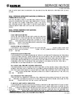
ANGELUS SANITARY CAN MACHINE COMPANY
SERVICE NOTICE
2 of 3
6/16/95-18033003
Motor Installation
A.
Install the Motor. Motor installation
should bring the Motor Shaft and Main
Drive Shaft within 1/4 inch of alignment.
Motor frames will vary, therefore, spacers
may have to be added under the Motor frame.
Center the Motor mounting holes with the
screws to provide room for angular
alignment later.
NOTE:
It is not suggested to use thin Shim Stock
to make this alignment. There is enough
Leaving 5/8 of an inch between the
allowable movement in the Sub-Base
Motor Shaft and Main Drive Shaft
slotted holes and Support Pad screws to
allows room for Coupling installation.
"zero" this in.
There should be approximately 5/8 of an
inch between the end of the Motor shaft
and the Main Drive Shaft for Coupling
installation or removal.
Dial Indicator Setup & Adjustment Parameters
Parts Required;
Dial Indicator with needle or plunger
Strap Clamp or Magnetic Base Mount
A.
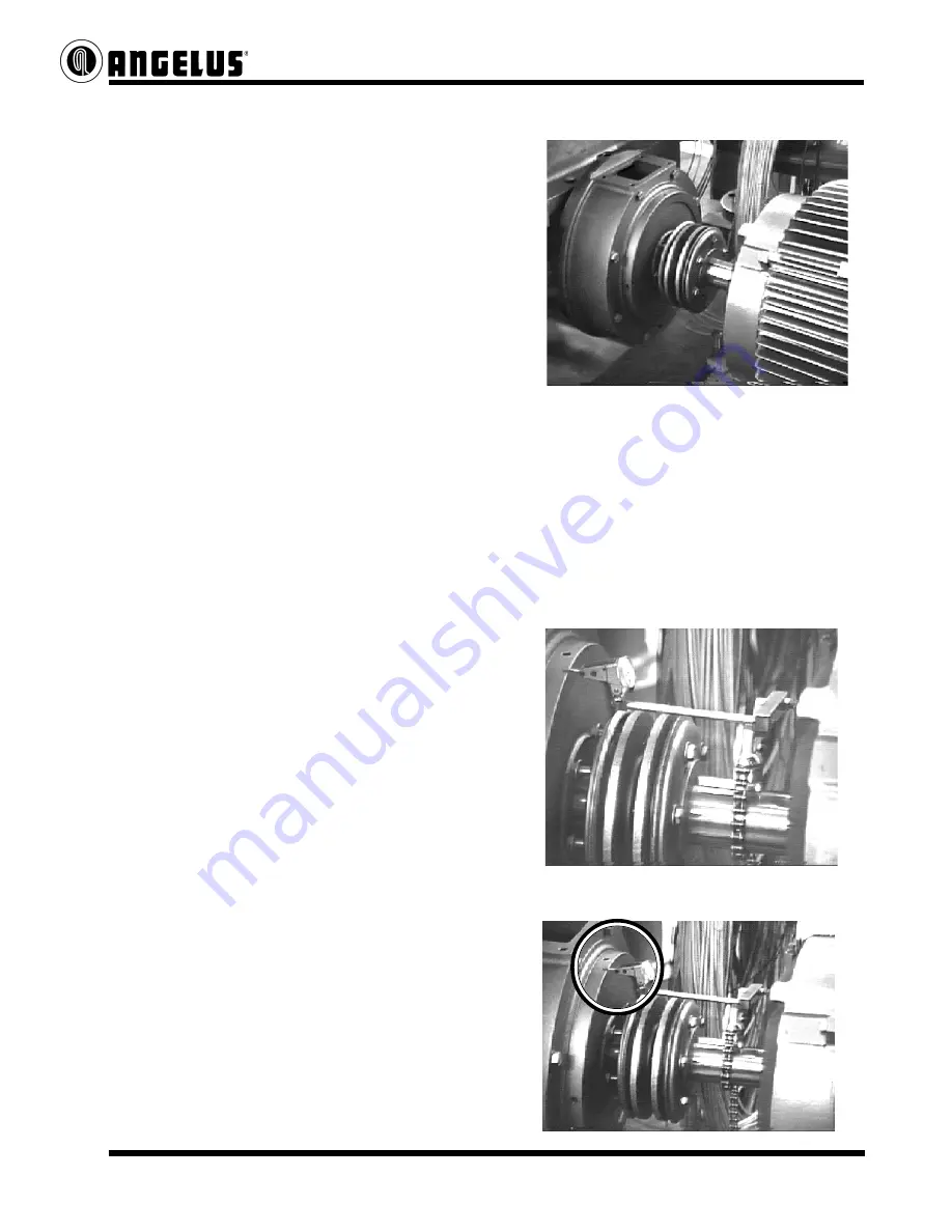
Attach a dial indicator and strap clamp
(a magnetic base can be used if a strap
clamp is not available) to the Motor Shaft.
Align the dial to first get a reading around
the outer perimeter of the Brake Housing
machined surface.
Dial set for the Perimeter Reading.
B.
Use jack screws and Pad screws to bring
vertical and side to side alignment between
the Motor Shaft and Brake Housing
within .005 of an inch. This is the Perimeter
alignment.


