background image


15 

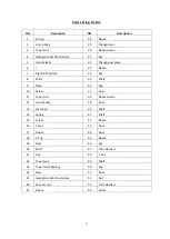
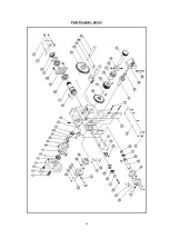
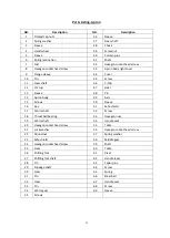
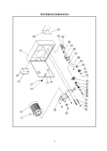
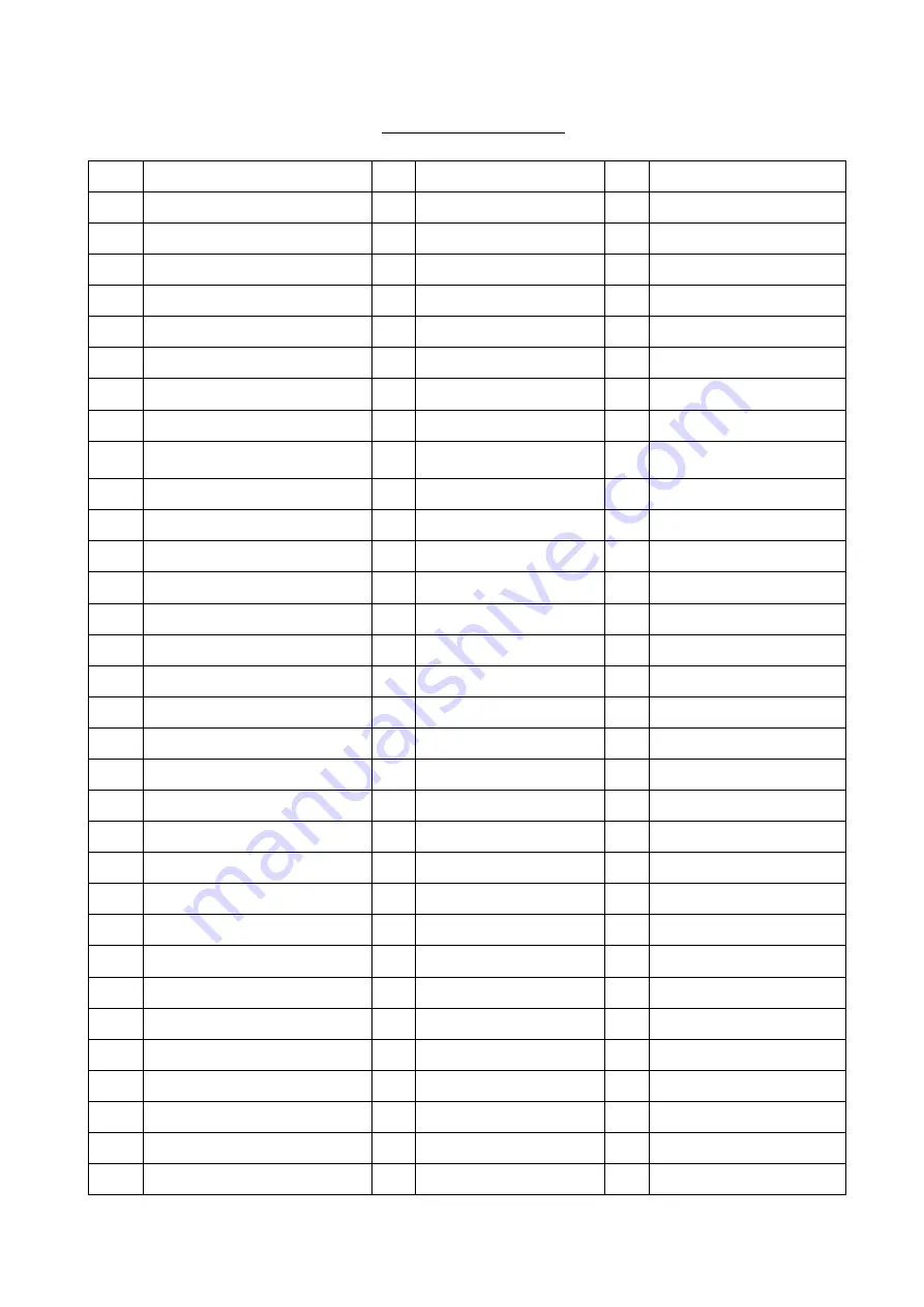
Parts Listing- Headstock 


NO.


Description 


V-belt type 700 

35 

Screw 

67 

C-Clip 

Spanner nut 

36 

Localing sleeve 

68 

Middle shaft 

Lock washer for circular nut 

37 

Washer 

69 

Thin flat key 

Spindle pulley 

38 

O-seal ring 

70 

Gear   

Taper roller bearing 

39 

Right Block 

71 

Gear   

Hexagon socket head screw 

40 

Oil Sight 

72 

C-Clip 

Pulley seat 

41 

Sleeve 

73 

Spanner nut 

Felt cover 

42 

C-Clip 

74 

Lock washer for circular nut 

Crossrecessed pan head screws 

43 

Left shifting fork 

75 

Hexagon socket head 
screw 

10 

Plain washers 

44 

Shifting fork shaft 

76 

Sleeve 

11 

Lathe head 

45 

Right shifting fork 

77 

Pressurize washer 

12-14  / 

46 

Sleeve 

78 

Sleeve spacer 

15 

Oil drain plug 

47 

Nut 

79 

Taper roller bearing 

16 

Oil cup 

48 

Plain washers 

80 

C-Clip 

17 

C-Clip 

49 

Gear 

81 

Gear   

18 

Cover 

50 

Felt cover 

82 

Taper roller bearing 

19 

Change Gear 

51 

Sleeve 

83 

Pressurize washer 

20 

Sleeve spacer 

52 

Taper roller bearing 

84 

Main shaft bearing oil seal 

21 

Plain parallel key 

53 

Plain parallel key 

85 

Lathe spindle 

22 

Sleeve


54 

Output shaft 

86 

Plain parallel key 

23 

Gear 

55 

Plain parallel key 

87 

Sleeve spacer 

24 

Shaft 

56 

Gear   

88 

Gear   

25 

Screw 

57 

Gear   

89 

Gear   

26 

Left Block 

58 

Gear   

90 

Sleeve spacer 

27 

Handle lever 

59 

Sleeve spacer 

91 

Gear   

28 

Chock 

60 

Sleeve 

92 

Plain parallel key 

29 

Screw 

61 

Sleeve spacer 

93 

Plain parallel key 

30 

Set screws with cone point 

62 

Plain parallel key 

94 

Single shaft 

31 

Spring 

63 

Gear   

95 

Hexagon screw 

32 

Steel ball 

64 

Gear   

96 

Oil port plug 

33 

Handle seat 

65 

Gear   

97 

Transmission cover 

34 

Taper pins 

66 

C-Clip 


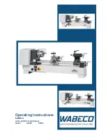
Summary of Contents for BL330E

Page 1: ......

Page 2: ... of the machine BE ALERT Do Not Use prescription or other drugs that may affect your ability or judgments to safely use this machine DISCONNECT the power source when changing tool bits and or any equipment NEVER leave an operating tool unattended ALWAYS keep blades knives or bits sharp and properly aligned ALWAYS keep all safety guards in place and ensure their proper function ALWAYS make sure tha...

Page 3: ...gth of work piece 700 mm Max Swing carriage 220mm Bed width 160mm Spindle Bore 38mm Spindle Taper MT 5 Spindle Speeds 12 Steps Spindle Speeds Range 60 90 120 160 220 300 380 500 640 850 110 1650rpm Max Lateral Stroke over tool post 160mm Max Longitudinal stroke of tool post 100mm Metric Thread kinds 17 Kinds Metric Thread range 0 5 4 mm Inch Thread kinds 24 Kinds Inch Thread range 9 40 TPI Longitu...

Page 4: ...r Change 25 Worm 06 Gear 26 Gear 07 Gear 27 Gear 08 Gear 28 Gear 09 Gear 29 Gear 10 Gear 30 Gear 11 Spindle Gear 31 Gear 12 Gear 32 Gear 13 Tool Post Lead Screw 33 Gear 14 Tool Post Nut 34 Gear 15 Tail Stock Lead Screw 35 Motor Pulley 16 Tool Post Nut 36 Gear 17 Longitudinal Screw 37 Gear 18 Longitudinal Nut 38 Gear 19 Cross Nut 39 Gear 20 Cross Lead Screw ...

Page 5: ...s this lathe is for the most part pre assembled at the factory there is not a great deal of assembly for the end user Line up the four bolt holes with the stand and carefully place the lathe on the stand Fig 3 Installation drawing After installation be sure to clean the antiseptic coat used to preserve and protect during shipping off the guide carriage tail stock change gear and pulley with a clea...

Page 6: ... Machine oil 2 days 7 Longitudinal lead screw Lead screw Gun Machine oil 2 days 8 Lathe bed guide Lathe bed Gun Machine oil 2 days 9 Tail stock sleeve Tailstock Gun Machine oil 2 days 10 Tailstock lead screw bush bearing Tailstock Gun Machine oil 2 days 11 Bearing pedestal Lathe bed Gun Machine oil 2 days 12 Cross nut lead screw Small carriage Gun Machine oil 2 days 13 Bearing bush Small carriage ...

Page 7: ...e plug MUST be plugged into a matching outlet that has been properly installed and grounded in accordance with ALL local codes and ordinances DO NOT MODIFY THE PLUG PROVIDED If the provided plug will not fit the electrical outlet have the proper outlet installed by a qualified licensed electrician IMPROPER CONNECTION of the equipment grounding conductor can result in risk of electrical shock The c...

Page 8: ... Feed Table Cutting threads and feeding movement can be performed by the manual use of the change gears and handle refer to Operating Controls Thread Feed Chart Fig 7 Operating Controls Fig 7 Thread Feed Chart ...

Page 9: ...tch 7 Self centering 3 Jaw Chuck 8 Handler of 4 way Tool Post 9 Tool Post Feeding Handler 10 Handle Lock for tailstock center 11 Lever to lock Tailstock 12 Tailstock hand wheel 13 Tailstock Offset Screw 14 Main Lead screw 15 Longitudinal cross feed handle 16 Handler of Auto Feed Half Nut 17 Carriage Cross Feed hand wheel 18 Apron feed hand wheel 19 Handle of forward reverse for lead screw 4 5 6 7 ...

Page 10: ...10 ...

Page 11: ...the centers The driver is driven by a catch or face plate Note Always use a small amount grease on the tailstock center to prevent center tip on overheating Fig 16 Fig 16 Taper Turing Using Tailstock Off set Work to a side angle it can be turned by off setting the tailstock the angle depends on the length of the workpiece Loosen the nut A Fig 17 handle C and two screws D then adjust the screw A to...

Page 12: ...llow the cutting tool to traverse back to the starting point Repeat these steps until you have obtained the desired results Change Gear Replacement 1 Disconnected the machine from the power source 2 Unscrew the two fastening screw and remove the protective cover 3 Loosen the locking screw C Fig 19 on the quadrant 4 Swing the quadrant D Fig 19 to the right 5 Unscrew the bolt E Fig 19 from the leads...

Page 13: ...ed nut on the back of spindle Tighten slotted nut until all end play is taken up The spindle should still revolve freely Tighten two hex socket cap screws Caution excessive tightening or preloading will damage the bearings Fig 22 Cross Slide Adjustment The cross slide is fitted with a gib strip A Fig 23 and can be adjusted with screw B Fig 23 fitted with lock nuts C Fig 23 Loosen the lock nuts and...

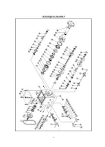
Page 14: ...14 Parts Diagram Headstock ...

Page 15: ...in plug 47 Nut 79 Taper roller bearing 16 Oil cup 48 Plain washers 80 C Clip 17 C Clip 49 Gear 81 Gear 18 Cover 50 Felt cover 82 Taper roller bearing 19 Change Gear 51 Sleeve 83 Pressurize washer 20 Sleeve spacer 52 Taper roller bearing 84 Main shaft bearing oil seal 21 Plain parallel key 53 Plain parallel key 85 Lathe spindle 22 Sleeve 54 Output shaft 86 Plain parallel key 23 Gear 55 Plain parall...

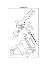
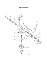
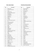
Page 16: ...16 Parts Diagram Trestle ...

Page 17: ... 34 Key 8 Shaft 35 Shaft 9 Base 36 Key 10 Screw 37 Gear 11 Taper pins 38 Sleeve spacer 12 Handle seat 39 Gear 13 Steel ball 40 Shaft 14 Spring 41 Shaft 15 Screw 42 Sleeve 16 Cover 43 Gear 17 Sleeve 44 Gear 18 C Clip 45 Sleeve 19 Gear 46 Key 20 Shaft 47 Plain washers 21 Key 48 T Nut 22 Taper pins 49 Shaft 23 Taper roller bearing 50 Key 24 Base 51 Gear 25 Hexagon socket head screw 52 Nut 26 Spanner ...

Page 18: ...18 Parts Diagram Bed ...

Page 19: ...ew 46 Behind board 14 Chock 47 Hexagon nuts 15 Shield 48 Set screws with cone point 16 Middle carriage 49 Hexagon socket head screw 17 Oil cup 50 Rivet 18 Hexagon socket head screw 51 Table 19 Washer 52 Bed 20 Set screws with cone point 53 Oil cup 21 Oil cup 54 Hexagon socket head screw 22 Plain washers 55 Right pedestal 23 Hexagon head bolts 56 Taper pins 24 Taper pins 57 Taper pins 25 Hexagon so...

Page 20: ...20 Parts Diagram Apron ...

Page 21: ...eeve 48 Pin 14 Apron body 49 Axis 15 Screws 50 Sleeve 16 Key 51 Safe shield 17 Worm shaft 52 Screw 18 Thrust ball bearing 53 Hexagon nuts 19 Worm shaft 54 Handle seat 20 Hexagon socket head screw 55 Table 21 Lock washer 56 Hexagon socket head screw 22 Round nut 57 Spring washer 23 Safe shield 58 Middle gear 24 Hexagon socket head screw 59 Shaft 25 Gear 60 Table 26 Shifting fork 61 Rivet 27 Shiftin...

Page 22: ...22 Parts Diagram Tailstock ...

Page 23: ...n parallel key 15 T nut 16 Taper pins 16 Change gear plate 17 Shaft 17 Plain washers 18 Oil cup 18 Plain parallel key 19 Sleeve 19 Sleeve 20 Handle lever 20 Hexagon thin nuts 21 Handle ball 21 Gear 22 Hexagon socket head screw 22 Sleeve 23 Spring lamination 23 Hexagon socket head screw 24 Dial 24 Change Gear 25 Sleeve 25 Change Gear 26 Hand wheel 26 Plain parallel key 27 Plain washers 27 Sleeve 28...

Page 24: ...24 Parts Diagram Change Gear Box ...

Page 25: ...d pilot lamp strictly 2 The sensitivity and reliability of mechanical control device Control levers for forward and reverse main spindle automatic feeds and threads change should be sensitive and reliable Automatic control devices for longitudinal and cross feed gear change threads change carriage and spindle direction change should be accurate also 3 Coolant system Check the quantity of coolant o...

Page 26: ...d readjust the tensile strength of V belt Trouble Shooting Problem Possible Cause Remedy Too chatters Gibs too loose on table Unused feeds not locked Tool not on center Improper tool shape Tool dull Readjust gibs Lock all axes but one moving Center tool Reshape sharpen replace tool Depth of cut is not consistent Quill moving Setup wrong Lock quill Make sure setup is parallel to table Hole is off c...

Reviews: