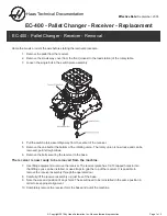


7
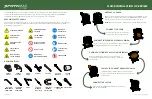
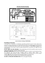
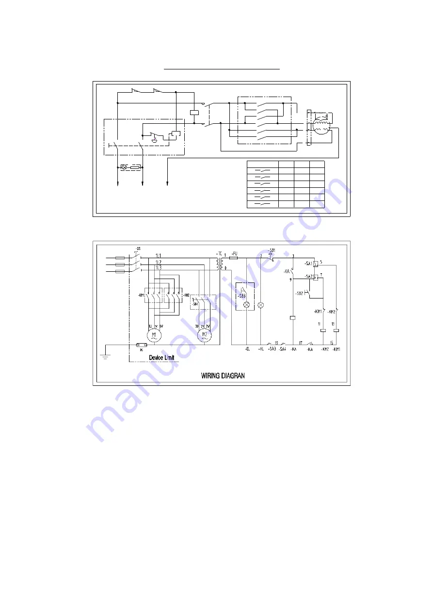
Electrical System Drawing
14
23
13
SB2
N
L
SB1
24
26
KM
KM
10
2
4
6
8
7
5
3
1
9
11
12
Z 2
U1
K
V 2
Z1
M
∽
Y L -9 0 L 4 1. 1 K W
C 1
C 2
V 1
(
Z 1
)
U 2
U
<
A1
AC220V/240V
50HZ/60HZ
HL
25
SQ1
PE
SQ2
ZH-A
KJD17B
R
*
*
*
*
O
F
*
*
*
*
1
2
3
4
5
6
7
8
9
10
11
12
Fig5. Electric System Drawing (SINGLE PHASE)
Fig6. Electric System Drawing (THREE PHASES)
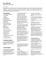
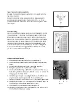
Grounding Instructions
In the event of a malfunction or breakdown, grounding provides the path of least resistance for
electrical current and reduces the risk of electrical shock. This tool is equipped with an electrical cord
that has an equipment grounding conductor and a grounding plug. The plug
MUST
be plugged into a
matching outlet that has been properly installed and grounded in accordance with
ALL
local codes
and ordinances.
DO NOT MODIFY THE PLUG PROVIDED.
If the provided plug will not fit the electrical outlet, have the
proper outlet installed by a qualified licensed electrician.
IMPROPER CONNECTION
of the equipment grounding conductor can result in risk of electrical shock.
The conductor wire with the green insulation (with or without yellow stripes) is the
equipment-grounding conductor. If repair or replacement of the electrical cord or cord or plug is
required,
DO
not
connect the equipment grounding conductor to a live terminal.
If in doubt about these instructions consult a qualified, licensed electrician.
USE ONLY A THREE-WIRE EXTENSION CORD
with a 3-prong grounding plug.
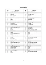
Summary of Contents for BL330E
Page 1: ......
Page 10: ...10 ...
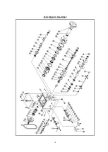
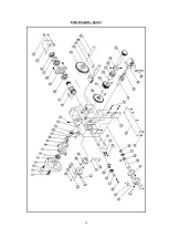
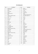
Page 14: ...14 Parts Diagram Headstock ...
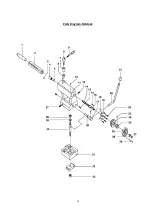
Page 16: ...16 Parts Diagram Trestle ...
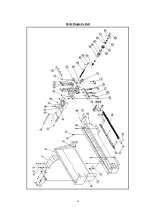
Page 18: ...18 Parts Diagram Bed ...
Page 20: ...20 Parts Diagram Apron ...
Page 22: ...22 Parts Diagram Tailstock ...