Copyright © 2019 AudioNote Kits
www.AudioNoteKits.com
audionotekits@rogers.com
Page 33
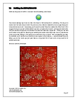
We have two 9 pin valve bases and four 8 pin CMC black valve bases. The 9 pin valve bases only
go in one way BUT the 8 pin valve bases have a key or slot on them that you must match up to
the PCB for correct installation. I suggest we not install the valve bases just yet – let's install
the resistors and then come back to the bases.
7.2.1 Resistor Installation
Let's start by installing all the resistors correctly and verifying.
Quantity
Designation
Description
2
R1-1,R1-2
470K
1/2W
2
R2-1,R2-2
10K
1/2W
2
R3-1,R3-2
330K
1/2W
2
R4-1,R4-2
100K
1W
2
R5-1,R5-2
470R
1/2W
2
R6-1,R6-2
100R
1/2W
2
R7-1,R7-2
33K
1/2W
2
R8-1,R8-2
33K
1/2W
2
R9-1,R9-2
22K
1/2W
2
R10-1,R10-2
270K
1/2W
2
R11-1,R11-2
270K
1W
2
R12-1,R12-2
10K
1/2W
2
R13-1,R13-2
10K
1/2W
1
R15
2K7
3W
2
R16-1,R16-2
1K8
1/2W
2
R17-1,R17-2
270R
10W
2
R18-1,R18-2
270R
10W
2
R19-1,R19-2
10R
3W
1
R20
470R
3W
4
R21-1,R21-2,R22-1,R22-2
220R
1/2W
1
R25
620R
1/4W
1
R26
22K
1W
2
R27-1,R27-2
220R
1W
2
R28-1,R28-2
220R
1W
1
R29
330K
2W
1
R30
47K
2W
When you see R1-1 – this means that R1 has a value of 470K (for example) and that there is a
right and left channel which are designated as R1-1 = 470K, R1-2 = 470K.
I suggest you use an ohm meter to verify the values of the resistors that you are installing.
Bend the leads at right angles so that the resistor fits into the holes. (There is an inexpensive

