Operator’s
Manual
pg.
10
Rev
E
4/2/12
Fat
Extraction
Process
Crude
Fat
Calculation
Crude Fat contained within a food or feed sample can be calculated using the following formula:
%
Crude
Fat
=
100
x
(W
2
–
W
3
)
W
1
Where:
W
1
=
Original
weight
of
sample
W
2
=
Weight
of
pre
‐
dried
sample
and
filter
bag
W
3
=
Weight
of
dried
sample
and
filter
bag after
extraction
For meat samples with > 15% fat and plant samples with > 20% fat:
%
Crude
Fat
=
100
x
((W
2
–
W
4
)
–
W
3
)
W
1
Where:
W
4
=
Weight
of
the
weigh
tin
Total
Fat
Calculation
If hydrolysis is done prior to fat extraction, then Total Fat contained within a food or feed sample can be calculated
using the following formula:
%
Total
Fat
=
100
x
(W
2
–
(W
3
+
(C
1
–
C
2
)))
W
1
Where:
W
1
=
Original
weight
of
sample
W
2
=
Weight
of
dried
sample,
filter
bag,
and
Diatomaceous
Earth
(DE)
after
hydrolysis
W
3
=
Weight
of
dry
extracted
sample,
filter
bag,
and
DE
C
1
=
Blank
filter
bag
dry
weight
after
hydrolysis
C
2
=
Blank
filter
bag
weight
after
extraction
Fat
Extraction
Support
Items
The following support items are needed to perform the fat extraction procedure:
Item
Recommended
Product
Electronic Balance with four-place readout
ANKOM #TB Balance Hardware
ANKOM #TBS Balance Software
Filter Bags
ANKOM #XT4
Bag Holder (used for adding sample to an empty filter bag)
ANKOM #101.2
Heat Sealer for sealing the filter bags
ANKOM #1915 (120V), #1920 (220V)
Solvent Resistant Marker
ANKOM #F08
Desiccant Pouch or Weigh Tin Desiccator for drying
ANKOM #X45, #X49
Oven for drying (capable of maintaining 102°C±2°)
ANKOM #RD (120V), #RDI (220V)
Ventilated oven trays to allow for sufficient oven air flow
-----------------
Weigh Tins (used with samples of > 20% fat)
-----------------
Sample
-----------------
Spoon
-----------------
Summary of Contents for XT10
Page 2: ...This page intentionally left blank ...
Page 4: ...This page intentionally left blank ...
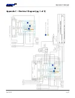
Page 25: ...Operator s Manual Rev E 4 2 12 pg 25 Appendix C Electrical Diagram pg 1 of 3 ...
Page 26: ...Operator s Manual pg 26 Rev E 4 2 12 Appendix C Electrical Diagram pg 2 of 3 ...
Page 27: ...Operator s Manual Rev E 4 2 12 pg 27 Appendix C Electrical Diagram pg 3 of 3 ...


