background image


11 


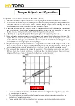
To adjust the torque on these screwdrivers. Proceed as follows :   

1.


Determine the torque output of the tool by checking a tightened fastener with a torque wrench. 

2.


Increase or decrease the torque by rotating torque Adjusting Ring. Rotating the Ring clockwise to 

a higher number on the torque Scale increase torque output while rotating  the Ring 

counterclockwise to a lower number decreases the torque output. 

3.


Check the adjustment with a torque wrench. A number of factors will affect torque output from 

one job to another. Final  torque adjustment should be made at the job through a of series of 

gradual increase. Always start below the desired torque and work upward. 

4.


Adjust the bit torque by changing the driving in length of the adjust ring at the end. 

5.


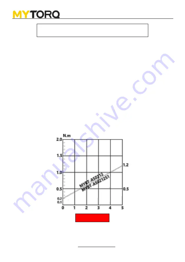
The relationship between torque scale and bit torque is as shown Ring, in the torque diagram. The 

figures of torque scale do not indicate bit torque values. However, the clamping torque of screw 

itself is different form type, size, material of the screw and the material of its mating part. Use it 

as standard to obtain an appropriate clamping torque. 

6.


The (Return torque method) in which once-clamped screw is returned with torque wrench or the 

like is available as one of torque control methods however, note that the measured values by the 

return torque method generally appear in 10%~30% lower than the actually clamping torque. 

7.


The torque checker measures the torque of screwdriver. The clamping torque of screw itself is 

different from the clamped conditions. Understand the correlation between clamping torque 

values and the torque checker values perform the torque control properly. 


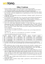
1.


In reverse rotation, the clutch is turned off when a screw is tightened at large torque, set same   

or higher torque to unscrew. 

2.


The number from zero to eight on the Torque Scale are reference number only and not an 

indication of actual torque output. 

3.


Please refer to ANLIDAR website http://www.anlidar.com for the detail component list.   


Torque Adjustment Operation 


CAUTION 

Summary of Contents for MYTORQ MYBT-AS0212

Page 1: ...al Cordless Brushless Power Torque Screwdrivers Series OPERATION AND MAINTENANCE MANUAL ANLIDAR INDUSTRIAL CO LTD http www anlidar com Y2F228A 3E 001 Rechargeable TYPE Automatic Brushless Series MYBT AS0212 MYBT AS0212S1 ...

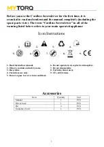
Page 2: ...refers to your main operated appliance Icon Instructions 1 2 3 4 1 2 3 4 5 6 7 8 9 1 Read instruction manual 6 Do not operate in an explosive atmosphere 2 Observe caution and safety notes 7 Do not disassemble 3 Recyclable 8 Forbid to throw away 4 For indoor use only 9 CE certification 5 Do not expose to wet or rain conditions Accessories Item Quantity Unit Manual 1 PCS Driver hook 1 PCS Bit 2 PCS ...

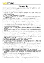
Page 3: ...age of working conditions On the contrary the purposes of the waist hook is convenient to put the device away and easier to keep it out of reach of children 9 Look after either the device or the battery carefully and have any damaged parts repaired by an authorized or qualified shop Always keep the tool nice and clean pay attention on the machine grease which might ruin the tool 10 Disconnect the ...

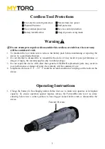
Page 4: ...le the device it may result in poor performance or danger of injury the warranty applies only to initial package 3 Do not repair the device with other than genuine ANLIDAR replacement parts may result in poor performance or danger of injury the warranty will be considered void 4 temperature between 0 C 35 C would be an ideal condition of carrying out the tasks on the device Operating Instructions ...

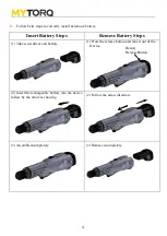
Page 5: ...move Battery Steps 1 Take screwdriver and battery 1 Press the release button and take it out of the Device 2 Insert the rechargeable battery into the device follow by the arrow as showing 2 Follow the arrow direction 3 Assembled completely 3 Removed completely Battery Release Button ...

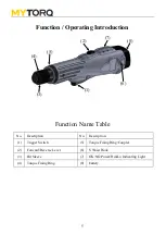
Page 6: ...n Function Name Table No Description No Description 1 Trigger Switch 5 Torque Fixing Ring Coupler 2 Forward Reverse Lever 6 S Waist Hook 3 Bit Sleeve 7 OK NG Power Hi Lo Indicating Light 4 Torque Fixing Ring 8 battery 8 1 6 3 7 2 5 4 ...

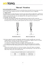
Page 7: ... showing always set the switch to neutral position when the screwdriver is not being used Forward screw Reverse unscrew 2 2 Hi Lo to change the speed of rechargeable screwdriver push Forward Reverse lever to the middle position release the switch for about 0 5 second and press trigger switch for 5 seconds then there will be a short beep sound to adjust the position 1 It represents Hi position when...

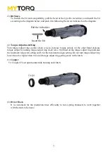
Page 8: ...orque output by turning torque adjust ring clock wise 0 printed on the torque adjust ring indicates the minimum torque for setting and 8 for the maximum torque setting Do not turn torque adjust ring lower than 0 or higher than 8 to avoid torque adjust ring getting stuck with clutch 5 Coupler 5 1 Coupler Fixed upside underside housing and clutch 6 Driver Hook It is convenient for the production lin...

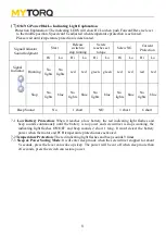
Page 9: ...ect the battery power when the motor and PCB temperature protection are activated 7 2 Temperature Protection The red indicating light flashes and beep sounds 9 times 7 3 Sleep Power Saving Mode It will enter sleep mode when the screwdriver stopped for about 5 seconds press the lever can wake up sleep The power will be cut off when sleep more than 24 seconds press the switch can restore power Signa...

Page 10: ...When adjusting the torque for safety purpose should stop the screwdriver completely and set the switch to neutral position It could prevent the user from turning the tool on accidentally 11 During operation the switch has been changed accidentally that the device will enable its self protecting mode which is power off Re start the tool when this happen 12 Each operational torque setting using time...

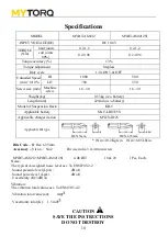
Page 11: ...on totol value an m Vncertainty totol K 1 5 m CAUTION SAVE THE INSTRUCTIONS DO NOT DESTROY MODEL MYBT AS0212 MYBT AS0212S1 INPUT VOLTAGE DC DC 10 8V TORQUE N m hard joints 0 2 1 2 0 2 1 2 soft joints 80 0 2 0 96 0 2 0 96 Torque accuracy 3 Torque adjustment Stepless Duty cycle 1 0s ON 3 0s OFF Unloaded Speed min 1 10 HI 1000 500 LO 700 350 Screw size mm Machine screw 1 6 3 0 1 6 3 0 Weight kg 0 53k...

Page 12: ... values However the clamping torque of screw itself is different form type size material of the screw and the material of its mating part Use it as standard to obtain an appropriate clamping torque 6 The Return torque method in which once clamped screw is returned with torque wrench or the like is available as one of torque control methods however note that the measured values by the return torque...

Reviews: