background image

Plunger Pumps

 Operating Instructions and Parts Manual 

RSV Series Pumps

First Choice When Quality Matters

NORTH

AMERICA

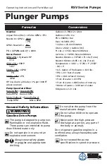
Formulas

Nozzles:

Impact Force (lbs.) = .0526 x GPM x 

PSI

Nozzle # = GPM x   4000
                       

          √ 

PSI

GPM= Nozzle # x    PSI  
                      

         √

4000

PSI = (GPM/Nozzle #)

 x 4000

Horse Power:

GPM x PSI = Hydraulic HP
    1714
GPM x PSI = EBHP
     1457
EBHP x 1457 = GPM
        PSI
EBHP x 1457 = PSI
      GPM
HP loss due to altitude = 3% per 1000 FT 
above sea level

Pump Speed and Flow:

Rated GPM = Desired GPM
Rated RPM    Desired RPM
Motor Pulley Ø = Pump Pulley Ø
 Pump RPM 

    Motor RPM

Conversions

Gallons x 3.785412 = Liters
Gallons x 128 = Oz.
PSI x .06896 = Bar
Bar x 14.5038 = PSI
1 inches = 25.4 millimeters
Liters x .2642  = Gallons (US)
Ft. Lbs. x 1.356 = Newton Meters
Inch Lbs. x .11298 = Newton Meters
Newton Meters x .737562 = Ft. Lbs. (force)
Newton Meters x 8.85 = In. Lbs. (force)
Temperature = 1.8(C° + 17.78) = F°,.555(F° 
- 32) = C°
1 U.S. Gallon of freshwater = 8.33 lbs.
1 PSI = 2.31 feet of water
1 PSI = 2.04 inches of mercury
1 Foot of water = .433 PSI
1 Foot of water = .885 inches of mercury
1 Meter of water = 3.28 feet of water
Kilograms x 2.2 = Lbs.

General Safety Information


WARNINGS

Gasoline Drive Pumps

The pump is designed to pump non-
flammable or non-explosive fluids. 
These pumps are intended to pump 

clean filtered water only. 

Do not operate in or around an 
explosive environment.  

Always wear safety glasses 
or goggles and appropriate 

clothing.

Do not alter the pump from the 
manufacturers design.

Do not allow children to operate 
the pump.
Never point the high-pressure 
discharge at a person, any part of 
the body or animals. 

Do not operate gasoline engines in a 
confined area; always have adequate 
ventilation.

Do not exceed the pump 
specifications in speed or pressure.

Summary of Contents for RSV 3400

Page 1: ...ra Form provide positive seating and extended life One piece connecting rods are special alloy aluminum bronze rods over 4 000 psi units oversized for strength and load disbursement These pumps are designed for gasoline driven systems Please read and save these instructions Read carefully before attempting to assemble install operate or maintain the product described Protect yourself and others by...

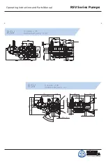
Page 2: ...First Choice When Quality Matters NORTH AMERICA Plunger Pumps Operating Instructions and Parts Manual RSV Series Pumps VERSION OLLOW SHAFT PUMP v 236 2 2 ª ª ª VERSION OLLOW SHAFT PUMP v 236 ...

Page 3: ...x 737562 Ft Lbs force Newton Meters x 8 85 In Lbs force Temperature 1 8 C 17 78 F 555 F 32 C 1 U S Gallon of freshwater 8 33 lbs 1 PSI 2 31 feet of water 1 PSI 2 04 inches of mercury 1 Foot of water 433 PSI 1 Foot of water 885 inches of mercury 1 Meter of water 3 28 feet of water Kilograms x 2 2 Lbs General Safety Information WARNINGS Gasoline Drive Pumps The pump is designed to pump non flammable...

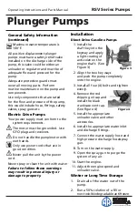
Page 4: ...r cords that are in good condition Never pull the unit by the power cord Never spray or clean the unit with water Failure to follow these warnings may result in personal injury or damage to property Installation Direct Drive Gasoline Pumps 1 Install the shaft key into the keyway and apply a light coating of anti seize on the engine shaft See Figure 3 2 Align the two key ways and push the pump comp...

Page 5: ...r any damage replace if necessary 3 Screw the machine screw into the hole on top of the valve cage approx 1 8 Using the diagonal pliers grasp the screw at the lowest reachable point Using the pump head as a base push down on the pliers the valve will lift out See Figure 6 4 Use a small probe to move the poppet up and down to assure that the valve is functioning properly and that no debris is stuck...

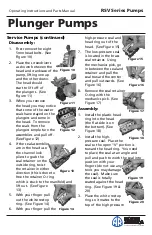
Page 6: ...r finger pull out the white restop ring See Figure 14 6 With your finger pull the high pressure seal and head ring out of the head See Figure 15 7 The low pressure seal is located in the brass seal retainer Using the mechanics pick go in between the seal and retainer and pull the seal toward the center and pull outwards See Figure 16 8 Remove the seal retainer O ring with the mechanics pick See Fi...

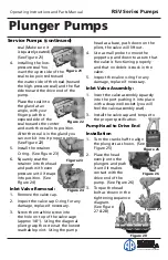
Page 7: ...ry 3 Screw the machine screw into the hole on top of the valve cage approx 1 8 Using the diagonal pliers grasp the screw at the lowest reachable point Using the pump head as a base push down on the pliers the valve will lift out 4 Use a small probe to move the poppet up and down to assure that the valve is functioning properly and that no debris is stuck in the valve 5 Inspect the valve o ring for...

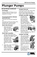
Page 8: ... damaged replace Place small amount of thread locker on the thread and tighten See Figure 31 Unloader Removal Tools required 3 8 rachet 22mm deep well socket crescent wrench small hammer 6mm x approximately 8mm or longer medium strength thread locker Unloader assembly removal 1 Using the 22mm socket rotate the pressure adjusting cap so both set of hexes are alligned Use screw to remove the complet...

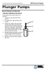
Page 9: ...rn brass pos 4 clockwise until it stops 3 Start pump watch pressure gauge and turn pos 2 using 3mm hex clockwise until recommended rated pressure is obtained Line pressure will be approximately 200 psi less then actual head pressure DO NOT set line pressure to rated 4 Release trigger and make sure there is minimal spike 200 300 psi Re peat this step two or three times 5 Tighten nut pos 3 down agai...

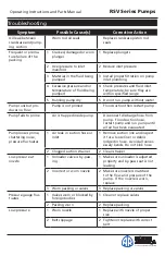
Page 10: ...Pump fails to prime Air is trapped inside pump Disconnect discharge hose from pump Flood suction hose restart pump and run pump until all air has been evacuated Pump looses prime chattering noise pressure fluctuates 1 Air leak in suction hose or inlet 1 Remove suction line and inspect it for a loose liner or debris lodged in hose Avoid all unnec essary bends Do not kink hose 2 Clogged suction stra...

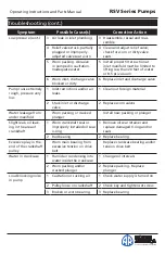
Page 11: ...aks 1 Clean out foreign material 2 Stuck inlet or discharge valve 2 Replace worn valves Water leakage from under manifold Worn packing or cracked plunger Install new packing or plunger Slight leak oil leak ing in the area of crankshaft 1 Worn crankshaft seal or improperly installed oil seal o ring 1 Remove oil seal retainer and replace damaged 0 ring and or seals 2 Bad bearing 2 Replace bearing Ex...

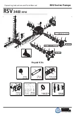
Page 12: ...gs Kit 2190 7 1 8 1 9 1 11 4 19 1 21 1 22 1 26 1 12 2 15 1 17 2 18 1 Water Seals Kit 2189 38 3 40 3 42 3 37 3 41 3 54 44 3 Support Ring Kit 2191 36 3 Unloader Kit 2280 15 14 13 12 11 10 9 8 7 6 5 4 2 3 2 1 Valves Kit 2186 35 6 Pistons Kit 2187 51 3 46 Oil Seals Kit 2188 64 O Rings Kit 2190 7 1 8 1 9 1 11 4 19 1 21 1 22 1 26 1 12 2 15 1 17 2 18 1 Water Seals Kit 2189 38 3 40 3 42 3 37 3 41 3 54 44 ...

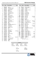
Page 13: ...1 4 G 2 34 2760180 Plug 442in lbs 3 35 2769050 Complete valve 6 36 2760220 Support ring 3 37 1342761 Gasket 3 38 1981580 Ring 1 39 1981570 Piston guide 3 40 770260 O Ring Ø23 52x1 78 3 41 1260440 Gasket 3 42 640070 O Ring Ø13 95x2 62 3 43 2760310 Spacer 3 44 1260460 Oil seal 3 45 2760010 Pump body 1 46 1266740 Bearing cap 1 47 1260790 Circlip Øi52 1 48 1780550 Snap ring 1 2760340 Bearing mr x 1 49...

Page 14: ...First Choice When Quality Matters NORTH AMERICA Plunger Pumps Operating Instructions and Parts Manual RSV Series Pumps Notes ...

Page 15: ...Plunger Pumps Operating Instructions and Parts Manual RSV Series Pumps First Choice When Quality Matters NORTH AMERICA Notes ...

Page 16: ...fluids not suitable for pump or accessory material construction Warranty does not apply to normal wear freight damage freezing damage or damage caused by parts or accessories not supplied by AR North America Inc Liability of manufacturer for warranty is limited to repair or replacement at the option of the manufacturer when such products are found to be of original defect or workmanship at the tim...

Reviews: