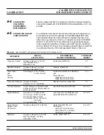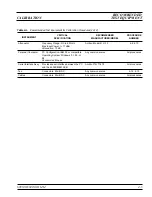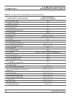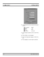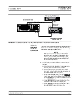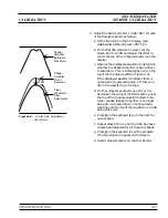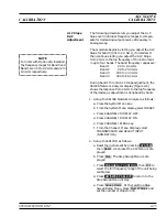
f. Using the key pad, enter the current date (in
any desired format). Then, press any termina-
tor key. The Calibration Status Menu display
changes to indicate calibration is in progress.
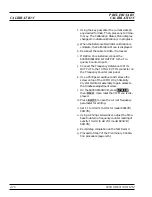
g. When the Reference Oscillator calibration is
complete, the Calibration Menu is displayed.
h. Reconnect the cable to A3J6, if removed.
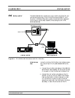
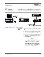
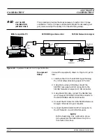
i. If Option 16 is installed, connect the
690XXB/691XXB
RF OUTPUT
to the Fre-
quency Counter Input 1.
j. Connect the Frequency Reference 10 MHz
OUTPUT to the 10 MHz EXT IN connector on
the Frequency Counter rear panel.
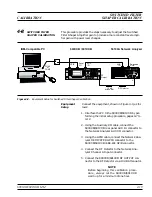
k. Use a Phillips screwdriver and remove the
screw on top of the 10 MHz High Stability
Crystal Oscillator assembly to gain access to
the timebase adjustment screw.
l. On the 690XXB/691XXB, press
SYSTEM
,
then
Reset
. Upon reset the CW Menu is dis-
played.
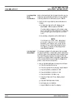
m.Press
Edit F1
to open the current frequency
parameter for editing.
n. Set F1 to 10 GHz (5 GHz for model 69017B/
69117B).
o. Using a Phillips screwdriver, adjust the time-
base to obtain a frequency counter reading of
exactly 10 GHz (5 GHz for model 69017B/
69117B).
p. Record step completion on the Test Record.
q. Proceed to Step 7 of the Preliminary Calibra-
tion procedure (page 4-15).
4-18
690XXB/691XXB MM
PRELIMINARY
CALIBRATION
CALIBRATION
Summary of Contents for 680 C Series
Page 4: ......
Page 5: ......
Page 13: ...Figure 1 1 Typical Series 690XXB 691XXB Synthesized CW Signal Generator Model 69187B Shown ...
Page 61: ......
Page 97: ......
Page 205: ......
Page 207: ......
Page 221: ......
Page 225: ......
Page 241: ......
Page 259: ......
Page 275: ......
Page 285: ......
Page 289: ......
Page 299: ......
Page 303: ......
Page 315: ......

