5-32
690XXB/691XXB MM
A10 ALC
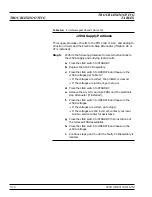
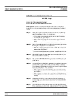
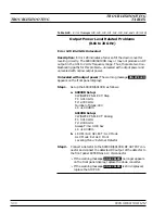
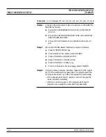
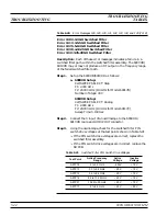
Error 121 Unleveled Indicator Failed
Error 122 Level Reference Failed
Error 123 Detector Log Amp Failed
Error 127 Detector Input Circuit Failed
Description: Error 121 indicates a failure of the circuit that alerts
the CPU whenever the RF output power becomes unleveled. Each of
the other error messages indicates a problem in the circuitry on the
A10 ALC PCB that provides control of the RF output power level.
Step 1.
Replace the A10 PCB, and run self-test.
q
If no error message is displayed, the problem is cleared.
q
If any of the error messages, listed above, is displayed,
contact your local Anritsu service center for assistance.
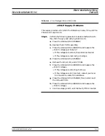
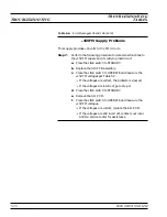
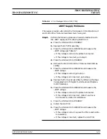
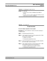
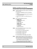
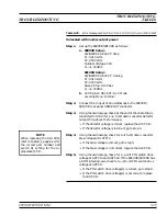
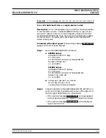
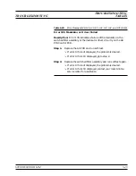
Error 142 Sample and Hold Circuit Failed
Description: Error 142 indicates a failure of the sample and hold cir-
cuitry on the A10 PCB. (This error occurs in 691XXB models only.)
Step 1.
Set up the 691XXB as follows:
a. Modulation: Square Wave On
Source: Internal
Frequency: 400 Hz
Polarity: High RF On
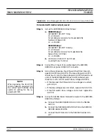
Step 2.
Using an oscilloscope, check for a 400 Hz square wave signal
at A9TP13.
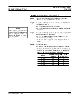
q
If the signal is present, replace the A10 PCB.
q
If the signal is not present, go to step 3.
Step 3.
Using the oscilloscope, check for a 400 Hz square wave sig-
nal at A6TP3.
q
If the signal is present, replace the A9 PCB.
q
If the signal is not present, replace the A6 PCB.
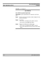
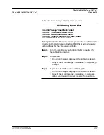
Table 5-17.
Error Messages 121, 122, 123, 127, 142, and 143 (1 of 2)
TROUBLESHOOTING
TROUBLESHOOTING
TABLES
Summary of Contents for 680 C Series
Page 4: ......
Page 5: ......
Page 13: ...Figure 1 1 Typical Series 690XXB 691XXB Synthesized CW Signal Generator Model 69187B Shown ...
Page 61: ......
Page 97: ......
Page 205: ......
Page 207: ......
Page 221: ......
Page 225: ......
Page 241: ......
Page 259: ......
Page 275: ......
Page 285: ......
Page 289: ......
Page 299: ......
Page 303: ......
Page 315: ......

