3-12
AMPLITUDE
MODULATION TEST
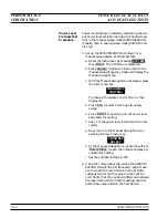
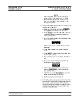
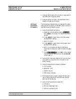
This procedure verifies the operation of the 691XXB amplitude modu-
lation input sensitivity circuit.
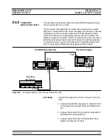
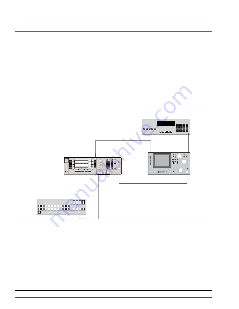
The RF output of the 691XXB is monitored on a Spectrum Analyzer
display. The (modulated) IF Output of the Spectrum Analyzer is moni-
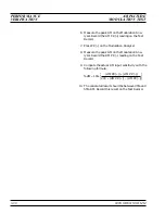
tored with a Modulation Analyzer. A 50% AM signal is set to a refer-
ence point on the Spectrum Analyzer. The actual modulation value is
then computed from the indicated Modulation Meter values. (The ab-
solute values of the AM PK+ and AM PK– readings are used in the
given formula to compensate for non-linearity errors in the test equip-
ment.)
Test Setup
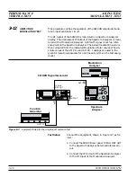
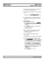
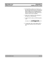
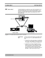
Connect the equipment, shown in Figure 3-7, as fol-
lows:
1. Connect the 691XXB rear panel
10 MHz REF OUT
to the Spectrum Analyzer External Reference In-
put.
2. Connect the IF Output of the Spectrum Analyzer
to the RF Input of the Modulation Analyzer.
3-28
690XXB/691XXB MM
PERFORMANCE
AMPLITUDE
VERIFICATION
MODULATION TEST
F u n c t i o n
G e n e r a t o r
O U T P U T
A M
I N
6 9 1 X X B S i g n a l G e n e r a t o r
R F
O U T P U T
1 0 M H z
R E F O U T
E X T
R E F I n p u t
R F I n p u t
R F I n p u t
I F O u t p u t
M o d u l a t i o n
A n a l y z e r
S p e c t r u m
A n a l y z e r
Figure 3-7.
Equipment Setup for the Amplitude Modulation Test
Summary of Contents for 680 C Series
Page 4: ......
Page 5: ......
Page 13: ...Figure 1 1 Typical Series 690XXB 691XXB Synthesized CW Signal Generator Model 69187B Shown ...
Page 61: ......
Page 97: ......
Page 205: ......
Page 207: ......
Page 221: ......
Page 225: ......
Page 241: ......
Page 259: ......
Page 275: ......
Page 285: ......
Page 289: ......
Page 299: ......
Page 303: ......
Page 315: ......


