2-5
RF DECK ASSEMBLIES
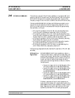
The primary purpose of the RF deck assembly is to generate CW and
swept frequency RF signals and route these signals to the front panel
RF OUTPUT
connector. It is capable of generating RF signals in the
frequency range of 0.01 to 65 GHz (0.00001 to 65 GHz with Option 22).
The series 690XXB/691XXB synthesized CW/signal generators use a
single YIG-tuned oscillator. All other frequencies, except for 0.01 to
10 MHz, are derived from the fundamental frequencies generated by
this oscillator, as follows:
q
RF output frequencies of 0.01 to 2 GHz are developed by down-
converting the fundamental frequencies of 6.51 to 8.5 GHz.
q
RF output frequencies of 0.01 to 2.2 GHz are developed by down-
converting the fundamental frequencies of 2 to 4.4 GHz using the
Digital Down Converter assembly, installed by Option 21A.
q
RF output frequencies of 20 to 40 GHz are produced by doubling
the fundamental frequencies of 10 to 20 GHz.
q
RF output frequencies of 40 to 65 GHz are produced by quadru-
pling the fundamental frequencies of 10 to 16.25 GHz.
q
RF output frequencies of 0.01 to 10 MHz are generated by the
A13 10 MHz DDS PCB, installed by Option 22.
The following paragraphs briefly describe the operation of the RF deck
assembly.
RF Deck Con-
figurations
All 690XXB/691XXB RF deck assemblies contain a
YIG-tuned oscillator, a switched filter assembly, and
a directional coupler. Beyond that, the configuration
of the RF deck assembly varies according to the par-
ticular instrument model. Block diagrams of the
various RF deck configurations are shown in the fol-
lowing figures:
q
Figure 2-4, page 2-21, is a block diagram of the
RF deck assembly for Model 69017B/69117B.
q
Figure 2-5, page 2-22, is a block diagram of the
RF deck assembly for Models 69037B/69137B
and 69047B/69147B.
q
Figure 2-6, page 2-23, is a block diagram of the
RF deck assembly for Model 69067B/69167B.
q
Figure 2-7, page 2-24, is a block diagram of the
RF deck assembly for Models 69077B/69177B,
69087B/69187B, and 69097B/69197B.
The block diagrams of the RF deck assemblies in-
clude all of the common RF components found in the
690XXB/691XXB RF deck assemblies. Refer to these
block diagrams during the descriptions of RF deck
operation presented in the following paragraphs.
690XXB/691XXB MM
2-19
FUNCTIONAL
RF DECK
DESCRIPTION
ASSEMBLIES
Summary of Contents for 680 C Series
Page 4: ......
Page 5: ......
Page 13: ...Figure 1 1 Typical Series 690XXB 691XXB Synthesized CW Signal Generator Model 69187B Shown ...
Page 61: ......
Page 97: ......
Page 205: ......
Page 207: ......
Page 221: ......
Page 225: ......
Page 241: ......
Page 259: ......
Page 275: ......
Page 285: ......
Page 289: ......
Page 299: ......
Page 303: ......
Page 315: ......


