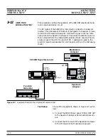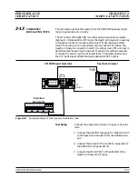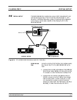
3. Connect the Output of the Function Generator to
the 691XXB front panel
AM IN
.
4. Connect the
RF OUTPUT
of the 691XXB to the
Spectrum Analyzer RF Input.
AM Input
Sensitivity
Procedure
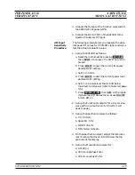
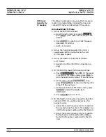
The following procedure lets you measure the abso-
lute peak AM values for a 50% AM signal and calcu-
late the actual modulation value.
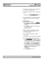
1. Set up the 691XXB as follows:
a. Reset the instrument by pressing
SYSTEM
,
then
Reset
. Upon reset, the CW Menu is dis-
played.
b. Press
Edit F1
to open the current frequency
parameter for editing.
c. Set F1 to 5 GHz.
d. Press
Edit L1
to open the current power level
parameter for editing.
e. Set L1 to a power level that is 6 dB below
maximum rated power (refer to Table 3-2, page
3-5).
f. Press
MODULATION
, then
AM
. At the result-
ing External AM Status menu, press
On / Off
to turn AM on.
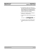
2. Set up the Function Generator for a 10 kHz sine
wave with an output level of
±
0.5 volts (1 volt
peak to peak).
3. Set up the Spectrum Analyzer as follows:
a. CF: 5.0 GHz
b. Span/Div: 0 Hz
c. RBW: 100 kHz
d. MIN Noise: Activate
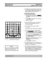
4. On the Spectrum Analyzer, adjust the reference
level to place the trace 6 to 8 dB below the top
graticule of the display.
5. Set up the Modulation Analyzer for:
a. AM PK(+)
b. 300 Hz High-Pass Filter
c. 20 kHz Low-Pass Filter
690XXB/691XXB MM
3-29
PERFORMANCE
AMPLITUDE
VERIFICATION
MODULATION TEST
Summary of Contents for 680 C Series
Page 4: ......
Page 5: ......
Page 13: ...Figure 1 1 Typical Series 690XXB 691XXB Synthesized CW Signal Generator Model 69187B Shown ...
Page 61: ......
Page 97: ......
Page 205: ......
Page 207: ......
Page 221: ......
Page 225: ......
Page 241: ......
Page 259: ......
Page 275: ......
Page 285: ......
Page 289: ......
Page 299: ......
Page 303: ......
Page 315: ......


