5.4 Generating Waveform Pattern
5-9
5.4 Generating Waveform Pattern
This section describes a series of operations for converting an
ASCII-format waveform pattern generated by external simulation
software to a waveform pattern that can be used by the
MG3700A/MG3710A/MG3710E/MG3740A using the Convert function of
the IQproducer
TM
for MG3700A/MG3710A/MG3710E/MG3740A.
Refer to Section 4.5 “File Conversion on Convert Screen” for details of
setting parameters.
<Procedure>
1. Click the
Reference
button and read the file to be converted.
2. The parameters related to the waveform pattern are enabled to be
input after reading the waveform pattern file. Input these
parameters as required according to the type and applications of the
waveform pattern.
3. Set the sampling rate.
The sampling rate indicates the speed of reading the waveform
pattern from an arbitrary waveform memory in the
MG3700A/MG3710A/MG3710E/MG3740A. Note that it is not the
speed after processing the interpolator within the
MG3700A/MG3710A/MG3710E/MG3740A.
When reading a W-CDMA waveform pattern having the over
sampling of
×
4, for example, set the sampling rate as follows:
3.84 Mcps
×
4 = 15.36 MHz
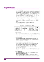
4. Select the cut off frequency for the low-pass filter.
This is available only for MG3700A.
The low-pass filter, which is inserted in the analog baseband route,
is used to remove an image component generated in the D/A
converter output. When AUTO is set, the cut off frequency is
automatically changed depending on the Sampling Rate setting as
shown in Table 5.4-1 below.
In Table 5.4-1, Interpolation indicates the scaling factor of the
interpolator of the arbitrary waveform generator. Since the image
components of the waveform pattern are raised to N-times frequency
based on the interpolation factor (N), the sufficient attenuation of
the image components can be assured by the low-pass filter. Also,
employing the interpolator improves the frequency characteristics
within the modulation band due to the 0 order hold of the D/A
converter output.


