6-6 A2 CPU Assembly and Hard Drive
Chapter 6 — Removal and Replacement Procedures
6-12
PN: 10370-10372 Rev. B
MG3702xA MM
6.
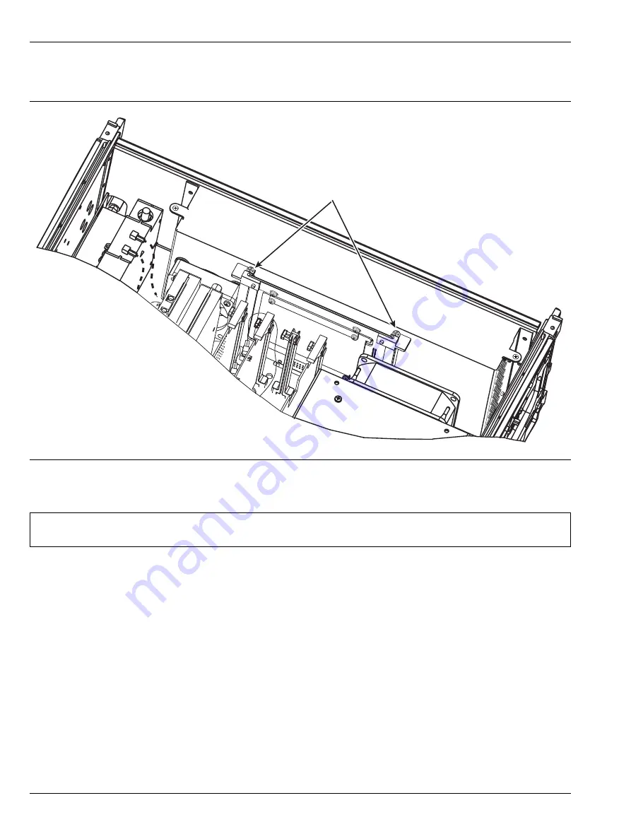
Remove the 2 screws at the top of the PCB that attach the HDD carrier board to the vertical brackets.
The PCB can be lifted up and removed.
7.
To install the A2 CPU PCB and HDD, reverse the removal process.
8.
Copy all files from the USB Flash Drive Calibration directory to the C:\Anritsu\MG37020A\Calibration
directory, making sure the Options.dat and SerialNumber.dat files
ARE NOT
overwritten or deleted.
If the calibration files were able to be saved and copied onto the new A2 CPU / HDD Exchange Assembly
then only a full verification needs to be performed.
If the calibration files were not able to be saved and copied onto the new A2 CPU / HDD Exchange
Assembly then a full calibration and verification needs to be performed.
Battery Replacement Procedure
below for the location of the processor battery (Anritsu part number 3-633-43 for CR2032 coin
battery)
1.
Lift the tab over the battery to remove.
After battery replacement, apply 2 drops of RTV compound to attach the edge of the battery to the battery
holder. This will ensure the battery cannot work loose during transport.
Figure 6-5.
HDD Removal
Note
When reconnecting the ribbon cable, the edge with the red stripe should be located to the right as
seen from the front of the instrument.
Remove 2 screws
and lift out HDD Carrier
Summary of Contents for MG3702xA Series
Page 4: ......
Page 5: ......
Page 8: ...TG 8 PN 10370 10372 Rev B MG3702xA MM ...
Page 24: ...1 12 Test Equipment List Chapter 1 General Information 1 10 PN 10370 10372 Rev B MG3702xA MM ...
Page 42: ...2 5 RF Deck Assemblies Chapter 2 Functional Description 2 18 PN 10370 10372 Rev B MG3702xA MM ...
Page 120: ...5 5 Troubleshooting Tables Chapter 5 Troubleshooting 5 24 PN 10370 10372 Rev B MG3702xA MM ...
Page 182: ...Index 4 PN 10370 10372 Rev B MG3702xA MM ...
Page 183: ......


