6-8 A4, A6, A8 PCBs
Chapter 6 — Removal and Replacement Procedures
6-14
PN: 10370-10372 Rev. B
MG3702xA MM
6-8
A4, A6, A8 PCBs
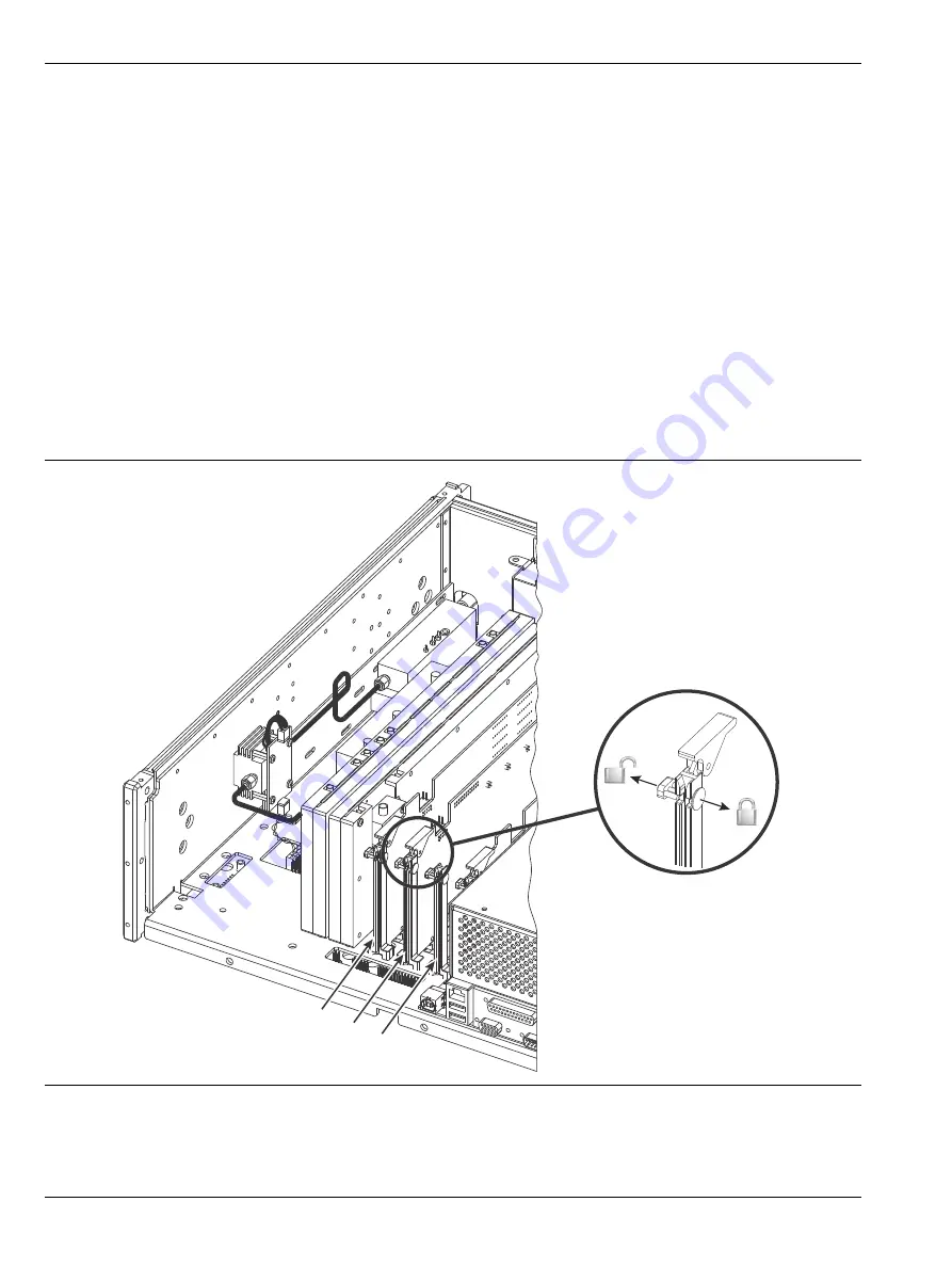
These PCBs are secured by a locking catch on each end of the board.
shows the locked and unlocked
positions of the catch. The PCB is unlocked when the circular tab is pushed inward.
Preliminary
Remove the front handles, rear feet, and chassis top and bottom covers as described in
.
Procedure
To release the A4, A6, or A8 PCB:
1.
Unplug all cables that are attached to the top of the board.
2.
Release the locking catches at both ends of the PCB.
3.
Lift the release tabs on each end and pull the PCB straight up to remove from the unit.
4.
To install the PCB, reverse the removal process.
5.
for the adjustments and verifications needed after replacement.
Figure 6-7.
A4, A6, A8 PCB Locking Catch
A8
A6
A4
Rear Panel
removed for clarity
Summary of Contents for MG3702xA Series
Page 4: ......
Page 5: ......
Page 8: ...TG 8 PN 10370 10372 Rev B MG3702xA MM ...
Page 24: ...1 12 Test Equipment List Chapter 1 General Information 1 10 PN 10370 10372 Rev B MG3702xA MM ...
Page 42: ...2 5 RF Deck Assemblies Chapter 2 Functional Description 2 18 PN 10370 10372 Rev B MG3702xA MM ...
Page 120: ...5 5 Troubleshooting Tables Chapter 5 Troubleshooting 5 24 PN 10370 10372 Rev B MG3702xA MM ...
Page 182: ...Index 4 PN 10370 10372 Rev B MG3702xA MM ...
Page 183: ......


