Chapter 4 — Adjustment
4-10 Level ALC Adjustment
MG3702xA MM
PN: 10370-10372 Rev. B
4-9
4-10 Level ALC Adjustment
This adjustment updates the ALC Calibration table.
Required Equipment
•
Anritsu ML2438A Power Meter
•
Anritsu MA2474D Power Sensor
•
Anritsu 41KC-10 10 dB Attenuator
Equipment Setup
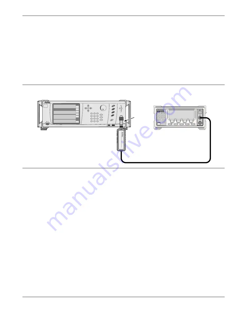
Connect the equipment as shown in
Procedure
1.
Power on the MG3702XA and allow the unit to warm up for 1 hour.
2.
Preset the unit by pressing the Preset hard key.
3.
Press
System
| Maint |
12345 | Enter
| Calibration | Level.
4.
Press
ALC Cals.
5.
Cal/zero the power sensor and set the sensor cal factor to 1 GHz.
6.
Connect the power sensor to a 10 dB attenuator and then connect the 10 dB attenuator directly to
the RF Output of the MG3702XA.
7.
Press
Run Cal | Next.
8.
Adjust the DAC value so the power meter reads –25.0 dBm, which is 10 dB below the desired level.
9.
Press
Next.
10.
Adjust the DAC value so the power meter reads –15.0 dBm, which is 10 dB below the desired level.
11.
Press
Next.
12.
Adjust the DAC value so the power meter reads –15.0 dBm, which is 10 dB below the desired Level.
13.
Press
Next.
14.
When instructed to enter the DAC value for 1 dB less than the maximum power, increase the DAC
until the power meter shows no increase in power.
Figure 4-3.
Level ALC Adjustment Setup
10 dB
Attenuator
MG37022A
Signal
Generator
Standby
Operate
ML2438A
MA2474D
MG3702xA
DUT
Summary of Contents for MG3702xA Series
Page 4: ......
Page 5: ......
Page 8: ...TG 8 PN 10370 10372 Rev B MG3702xA MM ...
Page 24: ...1 12 Test Equipment List Chapter 1 General Information 1 10 PN 10370 10372 Rev B MG3702xA MM ...
Page 42: ...2 5 RF Deck Assemblies Chapter 2 Functional Description 2 18 PN 10370 10372 Rev B MG3702xA MM ...
Page 120: ...5 5 Troubleshooting Tables Chapter 5 Troubleshooting 5 24 PN 10370 10372 Rev B MG3702xA MM ...
Page 182: ...Index 4 PN 10370 10372 Rev B MG3702xA MM ...
Page 183: ......


