13
2.3 Connecting the Power Cord
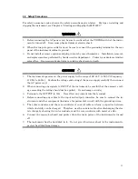
Check that the power switch on the front panel is turned off (switched to the (O) side).
Insert the power plug into an outlet, and connect the other end to the power inlet on the rear
panel. To ensure that the instrument is grounded, always use the supplied 3-pin power cord, and
insert the plug into an outlet with a ground terminal.
If the power cord is connected without the instrument grounded, there is a risk of receiving a fatal
electric shock. In addition, the peripheral devices connected to the instrument may be damaged.
When connecting to the power supply, DO NOT connect to an outlet without a ground terminal.
Also, avoid using electrical equipment such as an extension cord or a transformer.
If an emergency arises causing the instrument to fail or malfunction, disconnect the instrument
from the power supply by either turning off the power switch on the front panel (switch to the (O)
side), or by pulling out the power cord or the power inlet.
When installing the instrument, place the instrument so that an operator may easily operate the
power switch.
If the instrument is mounted in a rack, a power switch for the rack or a circuit breaker may be
used for power disconnection.
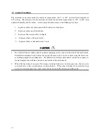
2.4 Running Applications Successfully
In addition to the Microsoft® MS-DOS® Operating System and Microsoft® Windows® Operating
System, the instrument has device control drivers and other software installed.
While you can make alterations to the Windows® operating environment via Control Panel or
Windows setup program, successful functioning of the application would be unpredictable if any
alteration is made beyond the scope of alterations mentioned in this operation manual.
Do not make alterations to the Windows® operating environment for any other purpose or in any
other method than those mentioned in this operation manual.
WARNING
CAUTION
Summary of Contents for MP1632C
Page 17: ...xvi...
Page 22: ...1 CHAPTER 1 OVERVIEW...
Page 30: ...9 CHAPTER 2 SETUP...
Page 35: ...14 Blank...
Page 36: ...15 CHAPTER 3 PANEL DESCRIPTION AND CONNECTIONS...
Page 45: ...24 Blank...
Page 46: ...25 CHAPTER4 STARTING AND STOPPING THE MP1632C...
Page 54: ...33 z Group box A frame or box that encloses a set of related controls...
Page 55: ...34 Blank...
Page 56: ...35 CHAPTER 5 DISPLAY DESCRIPTION...
Page 75: ...54 Blank...
Page 76: ...55 CHAPTER 6 OPERATING INSTRUCTIONS...
Page 114: ...93 CHAPTER 7 PERFORMANCE TEST...
Page 117: ...96 Blank...
Page 118: ...97 CHAPTER 8 MAINTENANCE SCRAPPING...
Page 121: ...100 Blank...
Page 122: ...101 APPENDIXES...
Page 127: ...106 Blank...

