17
Rear Panel
(1)
(2)
(3)
(4)
(5)
(6) (7)
(8)
(9)
(11)
(13)
F 8A
RS-232C
(COM1) Keyboard
M ouse
CRT
Optio n-01
~
Lin e 4 7.5-63 Hz
1kVA MAX
Pri nt er
(12)
Option-03 3.2G Internal Synthesizer
Clock(0.05-3.2GHz)
Output
1.0Vp-p 50Ω
!
Input
0.5
-
2
.
0Vp-p 50Ω
!
Output
1
.
0V p-p 50Ω
!
Lock(10MHz)
(10)
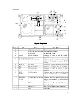
Fig. 3-2 Rear Panel
Number
Label
Name
Description
1
AC power connector
AC power connector
2
Functional earth terminal Functional earth terminal
3
Fuse holder
AC power fuse holder
4
Printer
Printer connector
Connector to which an external printer is
connected
5
RS-232C(COM1) RS-232C connector
Connector used to connect an external con-
troller to the instrument via an RS-232C
interface
6
Keyboard
Keyboard
Connector to which the keyboard is connected
7
Mouse
Mouse connector
Connector to which the mouse is connected
8
CRT
VGA connector
Connector to which an external display is
connected
9
GPIB
(OPT01)
GPIB connector
Connector used to connect an external con-
troller to the instrument via an GPIB inter-
face
10
ETHERNET
(OPT02)
10BaseT(RJ-45) connector Connector used to connect an external con-
troller to the instrument via an ETHERNET
interface
11
Slot1
Slot in which 3.2G internal synthesizer op-
tion is inserted
12
Slots 2 to 4
Slots in which plug-in units are inserted
13
Fan
Cooling fan
Summary of Contents for MP1632C
Page 17: ...xvi...
Page 22: ...1 CHAPTER 1 OVERVIEW...
Page 30: ...9 CHAPTER 2 SETUP...
Page 35: ...14 Blank...
Page 36: ...15 CHAPTER 3 PANEL DESCRIPTION AND CONNECTIONS...
Page 45: ...24 Blank...
Page 46: ...25 CHAPTER4 STARTING AND STOPPING THE MP1632C...
Page 54: ...33 z Group box A frame or box that encloses a set of related controls...
Page 55: ...34 Blank...
Page 56: ...35 CHAPTER 5 DISPLAY DESCRIPTION...
Page 75: ...54 Blank...
Page 76: ...55 CHAPTER 6 OPERATING INSTRUCTIONS...
Page 114: ...93 CHAPTER 7 PERFORMANCE TEST...
Page 117: ...96 Blank...
Page 118: ...97 CHAPTER 8 MAINTENANCE SCRAPPING...
Page 121: ...100 Blank...
Page 122: ...101 APPENDIXES...
Page 127: ...106 Blank...

