background image

EN

29

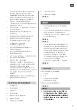
7.  Battery status indicator
8.  Load status indicator
9.  Charge status indicator

     FIG.   1

HOW TO USE

1.  Open the solar cell panel with the top 

side up.

2.  Remove the four supports from their 

velcro fasteners, unfold the supports to 
stretch out their support straps and place 
the support ends on a level surface.

     FIG.   2
     FIG.   3

3.  Position the solar panel as far as possible 

at right angles to the incoming sunlight 
to maximise solar radiation on the panel. 
If necessary put suitable supports under 
the panel so that it has the correct angle 
to the sunlight. Make sure that no part of 
the solar panel is shadowed, this reduces 
the output power. 
A = Good, B = Acceptable, C = Unacceptable

     FIG.   4

CONNECTION

Connect in the following order:
1.  Battery
2.  Load
3.  Solar cell panel as per wiring diagram. 
Disconnect in the reverse order.

     FIG.   5

     NOTE:   

•  The power switch must be switched off 

and the fuse removed/circuit breaker 
switched off when connecting the charge 
controller. Connect the positive and 
negative leads with the correct polarity.

against the ground, wall or roof. Its robust 
design with protective plastic film gives high 
efficiency and a long life. When the panel is 
not in use, it can easily be folded away to a 
compact case – which also has space for 
both the regulator and the cables.

•   3-stage intelligent PWM charging – boost 

charging, peak/equalisation charging and 
float charging.

•   Three battery alternatives – sealed, gel 

and wet-cell battery.

•   Button setting of battery type and load 

output.

•   Convenient and intuitive user interface.
•   Status lights for battery status.
•   Battery temperature compensation.
•   Comprehensive electronic safety functions.
•  Built-in protection diode for reverse cell 

current.

•  Built-in protection diode for reverse 

battery current.

•  Easy to carry, with corrosion-resistant 

stainless steel lifting eyes.

•  Dustproof, durable, soft. 
•   The output power of the product is 

proportional to the intensity of the 
incoming sunlight. Strong sunlight from a 
cloudless sky produces the most power. 
Clouds, seasonal variations in the 
elevation of the sun, contamination on 
the solar panel surface, incorrectly angled 
panel, and shadow reduce the output.

•  The output is also affected by transmission 

losses in cables and connection blocks.

CHARGE CONTROLLER PARTS

1.  Panel terminals
2.  Battery terminals
3.  Load terminals
4.  USB port
5.  Mounting hole 

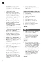
Ø

 4.5 mm

6.  Load switch

Summary of Contents for 014399

Page 1: ...den for fremtidig bruk Oversettelse av original bruksanvisning SE BRUKSANVISNING Viktigt L s bruksanvisningen f re anv ndning Spara den f r framtida bruk vers ttning av original bruksanvisning PL INS...

Page 2: ...Ved eventuelle problemer kan du kontakte v r kundeservice p telefon 67 90 01 34 www jula no Dbaj o rodowisko Nie wyrzucaj zu ytego produktu wraz z odpadami komunalnymi Produkt zawiera elektryczne kom...

Page 3: ...1 2...

Page 4: ...3 4...

Page 5: ...6 5...

Page 6: ...7...

Page 7: ...h g korrosionsbest ndighet och l ng livsl ngd Regulator med USB ing ng S KERHETSANVISNINGAR L s dessa anvisningar f re montering och anslutning av produkten Demontera inte produkten och f rs k inte n...

Page 8: ...nteras antingen h ngande eller lutande mot mark v gg eller tak Dess robusta design med skyddande plastfilm ger h g effektivitet och l ng livsl ngd N r panelen inte ska anv ndas kan den vikas ihop till...

Page 9: ...mm fr n batteriet Om v xelriktare ska anv ndas ska den anslutas direkt till batteriet inte till laddningsregulatorns lastplintar Vid stort effektbehov b r produkten anv ndas tillsammans med laddningsr...

Page 10: ...Lampa 2 Lampa 3 Lampa 4 Batteristatus Blinkar l ngsamt T nd T nd T nd Undersp nning Blinkar snabbt T nd T nd T nd Djupurladdning BILD 6 Batteristatusindikering vid stigande sp nning laddning Sl ckt S...

Page 11: ...st llning Sl ckt Sl ckt T nd Gel GEL Sl ckt Sl ckt Sl ckt V tcell FLd BATTERISP NNINGSGR NSER OCH LADDNINGSTIDER Sp nningsgr nserna nedan g ller f r 12 V system vid 25 C Multiplicera med 2 f r 24 V sy...

Page 12: ...s rjningen till den anslutna lasten kopplas fr n n r str mmen verstiger 1 25 g nger m rkstr mmen Anv ndaren m ste d minska den anslutna totala lasten och d refter trycka p laststr mbrytarknappen f r a...

Page 13: ...mpa 1 blinkar snabbt Undersp nning batteri Batterisp nningen har sjunkit under fr nkopplingsgr nsen och djupurladdningsskyddet har kopplat bort lasten fr n batteriet N r batterisp nningen terst llts t...

Page 14: ...ri 3 m Solcellepanelet monteres enten hengende eller hellende mot bakken vegg eller tak Den robuste SIKKERHETSANVISNINGER Les disse anvisningene du monterer og kobler til produktet Ikke demonter produ...

Page 15: ...h y effektivitet og lang levetid N r panelet ikke skal brukes kan det enkelt brettes sammen til en koffert som har plass til b de regulatoren og kablene Tretrinns intelligent PWM lading hovedlading t...

Page 16: ...det skal benyttes en vekselretter skal den kobles direkte til batteriet ikke til laderegulatorens lastplinter Ved stort effektbehov b r produktet brukes sammen med laderegulator for solcellepanelet f...

Page 17: ...mpe 3 Lampe 4 Batteristatus Blinker sakte Sl p Sl p Sl p Underspenning Blinker raskt Sl p Sl p Sl p Dyputlading BILDE 6 Batteristatusindikator ved stigende spenning lading Slukket Slukket Sl p Sl p 12...

Page 18: ...ket Sl p Gel GEL Slukket Slukket Slukket V tcelle FLd BATTERISPENNINGSGRENSER OG LADETIDER Spenninggrensene nedenfor gjelder for 12 V system ved 25 C og ganges med to for 24 V system Batteritype Forse...

Page 19: ...anger den nominelle str mmen Brukeren m da minske den totale tilkoblede lasten og deretter trykke p laststr mbryterknappen for koble til lasten igjen Kortslutningsvern Str mforsyningen til den tilkobl...

Page 20: ...nker raskt Underspenning batteri Batterispenningen har sunket under frakoblingsgrensen og dyputladingsbeskyttelsen har koblet lasten fra batteriet N r batterispenningen tilbakestilles til minst tilbak...

Page 21: ...niwa monokrystaliczne o du ym wsp czynniku wydajno ci i d ugiej ywotno ci ZASADY BEZPIECZE STWA Przed monta em i pod czeniem produktu przeczytaj niniejsze wskaz wki Nie demontuj produktu i nie pr buj...

Page 22: ...ej ciem USB Przew d z ko c wk do przy czania akumulatora 12 V 3 m Panel s oneczny do monta u w pozycji wisz cej lub pochylonej na ziemi cianie lub dachu Solidne wykonanie i warstwa ochronnej folii zap...

Page 23: ...umulatora maksymalnie 150 mm od akumulatora nale y zamontowa bezpiecznik o pr dzie wyzwalania 1 25 2 00 wi kszym od pr du znamionowego regulatora adowania Je li b dzie u ywany inwerter nale y go pod c...

Page 24: ...atora Miga powoli wieci si wieci si wieci si Zbyt niskie napi cie Szybkie miganie wieci si wieci si wieci si Ca kowite roz adowanie RYS 6 Wskazanie stanu akumulatora przy rosn cym napi ciu adowanie Zg...

Page 25: ...we Zgaszony Zgaszony wieci si elowy GEL Zgaszony Zgaszony Zgaszony Mokry FLd WARTO CI GRANICZNE NAPI CIA AKUMULATORA I CZAS ADOWANIA Progi napi cia obowi zuj dla uk adu 12 V przy temp 25 C Nale y pomn...

Page 26: ...zostaje od czony w momencie gdy warto pr du przekroczy 1 25 krotno pr du znamionowego U ytkownik musi w wczas ograniczy pod czony sprz t obci aj cy i nast pnie nacisn przycisk prze cznika sprz tu obc...

Page 27: ...napi cie akumulator Napi cie w akumulatorze spad o poni ej granicy wymuszaj cej wy czenie i zabezpieczenie przed ca kowitym roz adowaniem akumulatora od czy o sprz t obci aj cy Po przywr ceniu napi ci...

Page 28: ...ith USB port Cable with cable lugs for connection to 12 V battery 3 m The solar panel is mounted either suspended or sloping SAFETY INSTRUCTIONS Read these instructions before installing and connectin...

Page 29: ...with protective plastic film gives high efficiency and a long life When the panel is not in use it can easily be folded away to a compact case which also has space for both the regulator and the cable...

Page 30: ...rter is used it should be connected directly to the battery not to the load terminals on the charge controller For a large power requirement the product should be used together with a charging regulat...

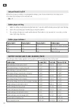
Page 31: ...ort circuit Battery status indicator Light 1 Light 2 Light 3 Light 4 Battery status Flashing slowly On On On Undervoltage Flashing rapidly On On On Over discharge FIG 6 Battery status for increasing v...

Page 32: ...ING TIMES The voltages limits below apply for 12 V system at 25 C Multiply by 2 for 24 V system Battery type Sealed SEL Gel GEL Wet cell FLd Overvoltage disconnection limit 16 0 V 16 0 V 16 0 V Chargi...

Page 33: ...The user must then reduce the connected total load and press the load switch button to reconnect the load Short circuit protection The power supply to the connected load is switched off if there is a...

Page 34: ...light 1 flashing rapidly Undervoltage battery The battery voltage has dropped below the disconnection limit and the over discharge protector has disconnected the load from the battery When the battery...

Reviews: