ENGLISH
61
months and reduces it during the winter months when the sun is lower in the sky. In simple terms it can
be said that if the primary objective of the solar collector is to generate hot tap water, this will allow a
reduction in the angle of the solar collector. If the solar collectors have been dimensioned to also
significantly contribute towards heating the house during the winter season, the collectors can to
advantage be aligned with an angle of about 50 to 70°. This will limit the output somewhat during the
summer, when in all probability the output from the solar collectors will be more than enough for the hot
tap water requirement (and any surplus heat generated will not lead to savings), but the output and
savings will increase during the autumn and winter months. The angle can in other words be used to
optimise the output from the solar collector in relation to the requirement and the objective during the
dimensioning of the system and thereby increase the annual savings. Vertical installation on a wall is fully
possible and the further north the solar collector is installed in Sweden the greater the advantage of a
greater angle on the collector, since this reduces the risk of it being covered by snow and enables the
reflections on the snow to be absorbed by the snow-free collector.
INSTALLATION OF ANSLUT SOLAR COLLECTOR
Before starting the installation
Make sure that the requisite safety equipment is available, e.g. safety harnesses and safety glasses etc.
We recommend scaffolding when installing on sloping roofs, alternatively safety harnesses for smaller
installations. Make sure that there is no risk of debris getting into the tubes or solar heating circuit during
the installation. Handle the vacuum tubes carefully and keep vacuum tubes, heat pipes, collector tubes
(manifold) and other installation parts clean during the installation.
Decide the positioning of the solar collector and how the installation is to be carried out with roof
attachments for sloping roofs or by installation on a 45° frame on the ground/flat roof.
Open the boxes with vacuum tubes (417031 package 1 of 3 and 2 of 3) before starting the installation.
Each vacuum tube is prepared for operation and the heat pipes have been centred in advance in the
respective vacuum tubes by means of heat transferring aluminium flanges. This makes the installation of
the vacuum tubes very simple and time-saving. Each vacuum tube is provided with a getter at the bottom
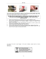
of the tube (the silver and shiny surface at the tip of the heat pipe). The function of the getter is to
guarantee that a high vacuum is maintained in the tube. If a vacuum tube should be damaged on
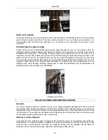
delivery, or if the vacuum is lost, the silver tip will become transparent in a short time (see image below).
If any of the vacuum tubes are damaged on delivery, please contact Anslut immediately to order a
replacement tube. One big advantage of the heat pipe system is that the actual heat pipes and the
aluminium flanges can easily be moved over to another vacuum tube, which considerably simplifies future
service work when necessary.
Summary of Contents for 417-031
Page 88: ...SVENSKA 8 Montering av kontrollpanel 1 Montering av bakstycke...
Page 89: ...SVENSKA 9 2 Montering av panel...
Page 94: ...SVENSKA 14 HT Set verhetningsskydd 1 Inst llningar...
Page 100: ...SVENSKA 20 2 Hur man s tter gr sv rdena f r automatiskt l ge...
Page 101: ...SVENSKA 21 3 Hur man ndrar viktiga v rden 4 Anv ndning av knappen...
Page 107: ...NORSK 27 Montering av kontrollpanel 1 Montering av bakstykke...
Page 108: ...NORSK 28 2 Montering av panel...
Page 114: ...NORSK 34 HT Set overopphetingsvern 1 Innstillinger...
Page 120: ...NORSK 40 2 Slik settes grenseverdier for automatisk modus...
Page 121: ...NORSK 41 3 Slik endres viktige verdier 4 Bruk av knappen...
Page 127: ...POLSKI 47 Monta panelu sterowania 1 Monta tylnej cz ci...
Page 128: ...POLSKI 48 2 Monta panelu...
Page 134: ...POLSKI 54 HT Set zabezpieczenie przed przegrzaniem 1 Ustawienia...
Page 140: ...POLSKI 60 2 Spos b ustawiania warto ci granicznych dla trybu automatycznego...
Page 141: ...POLSKI 61 3 Spos b zmiany istotnych warto ci 4 Spos b u ycia przycisku...
Page 147: ...ENGLISH 67 MOUNTING OF CONTROL PANEL 1 Mounting of back...
Page 148: ...ENGLISH 68 2 Mounting of panel...
Page 154: ...ENGLISH 74 HT Set overheating protection 1 Settings...
Page 160: ...ENGLISH 80 2 How to set limiting values for automatic mode...
Page 161: ...ENGLISH 81 3 How to change important values 4 Using the button...


